ZyXEL U-336R User Guide - Page 23
Front Panel Switches, Rear Panel Markings
 |
View all ZyXEL U-336R manuals
Add to My Manuals
Save this manual to your list of manuals |
Page 23 highlights
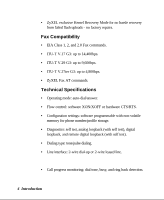
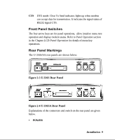
CTS DTE mode: Clear To Send indicator; lights up when modem can accept data for transmission. It indicates the signal status of RS232 signal CTS. Front Panel Switches The four arrow keys are for panel operations, allow intuitive menu tree operation and display modem status. Refer to Panel Operstion section in the Chapter LCD Panel Operation for details of menu key operations. Rear Panel Markings The U-336S/SA rear panels are shown below: Figure 2-3 U-336S Rear Panel Figure 2-4 U-336SA Rear Panel Explanations of the connectors and switch on the rear panel are given below. • POWER Installation 9
-
 1
1 -
2
-
3
-
4
-
5
-
6
-
7
-
8
-
9
-
10
-
11
-
12
-
13
-
14
-
15
-
16
-
17
-
 18
18 -
 19
19 -
 20
20 -
 21
21 -
 22
22 -
 23
23 -
 24
24 -
 25
25 -
 26
26 -
 27
27 -
 28
28 -
29
-
30
-
31
-
32
-
33
-
34
-
35
-
36
-
37
-
38
-
39
-
40
-
41
-
42
-
43
-
44
-
45
-
46
-
47
-
48
-
49
-
50
-
51
-
52
-
53
-
54
-
55
-
56
-
57
-
58
-
59
-
60
-
61
-
62
-
63
-
64
-
65
-
66
-
67
-
68
-
69
-
70
-
71
-
72
-
73
-
74
-
75
-
76
-
77
-
78
-
79
-
80
-
81
-
82
-
83
-
84
-
85
-
86
-
87
-
88
-
89
-
90
-
91
-
92
-
93
-
94
-
95
-
96
-
97
-
98
-
99
-
100
-
101
-
102
-
103
-
104
-
105
-
106
-
107
-
108
-
109
-
110
-
111
-
112
-
113
-
114
-
115
-
116
-
117
-
118
-
119
-
120
-
121
-
122
-
123
-
124
-
125
-
126
-
127
-
128
-
129
-
130
-
131
-
132
-
133
-
134
-
135
-
136
-
137
-
138
-
139
-
140
-
141
-
142
-
143
-
144
-
145
-
146
-
147
-
148
-
149
-
150
-
151
-
152
-
153
-
154
-
155
-
156
-
157
-
158
-
159
-
160
-
161
 |
 |

Installation
9
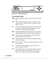
CTS
DTE mode: Clear To Send indicator; lights up when modem
can accept data for transmission. It indicates the signal status of
RS232 signal CTS.
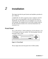
Front Panel Switches
The four arrow keys are for panel operations,
allow intuitive menu tree
operation and display modem status. Refer to Panel Operstion section
in the Chapter
LCD Panel Operation
for details of menu key
operations.
Rear Panel Markings
The U-336S/SA rear panels are shown below:
Figure 2-3 U-336S Rear Panel
Figure 2-4 U-336SA Rear Panel
Explanations of the connectors and switch on the rear panel are given
below.
•
POWER