Acer G330 User Manual - Page 54
Lay down the HSF in an upright position-with the thermal, from the mainboard.
 |
UPC - 750519177044
View all Acer G330 manuals
Add to My Manuals
Save this manual to your list of manuals |
Page 54 highlights
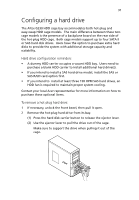
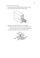
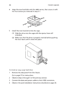
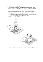
36 3 System upgrade 4 Remove the HSF from the chassis. The HSF type will depend on the default processor model. The figures below show the HSF types available for the Altos G330 system. (1) Disconnect the processor HSF cable from its mainboard connector. (2) Loosen the four HSF mounting pins. (3) Twist the HSF sightly to break the thermal grease bond loose. Once the thermal grease bond is broken, lift the HSF away from the mainboard. (4) Lay down the HSF in an upright position-with the thermal patch facing upward. Do not let the thermal patch touch the work surface. 5 Use an alcohol pad to wipe off the thermal grease from both the HSF assembly and the processor socket retention plate.
-
 1
1 -
2
-
3
-
4
-
5
-
6
-
7
-
8
-
9
-
10
-
11
-
12
-
13
-
14
-
15
-
16
-
17
-
18
-
19
-
20
-
21
-
22
-
23
-
24
-
25
-
26
-
27
-
28
-
29
-
30
-
31
-
32
-
33
-
34
-
35
-
36
-
37
-
38
-
39
-
40
-
41
-
42
-
43
-
44
-
45
-
46
-
47
-
48
-
 49
49 -
 50
50 -
 51
51 -
 52
52 -
 53
53 -
 54
54 -
 55
55 -
 56
56 -
 57
57 -
 58
58 -
 59
59 -
60
-
61
-
62
-
63
-
64
-
65
-
66
-
67
-
68
-
69
-
70
-
71
-
72
-
73
-
74
-
75
-
76
-
77
-
78
-
79
-
80
-
81
-
82
-
83
-
84
-
85
-
86
-
87
-
88
-
89
-
90
-
91
-
92
-
93
-
94
-
95
-
96
-
97
-
98
-
99
-
100
-
101
-
102
-
103
-
104
-
105
-
106
-
107
-
108
-
109
-
110
-
111
-
112
-
113
-
114
-
115
-
116
-
117
-
118
-
119
-
120
-
121
-
122
-
123
-
124
-
125
-
126
-
127
-
128
-
129
-
130
-
131
-
132
-
133
-
134
 |
 |

3 System upgrade
36
4
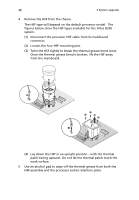
Remove the HSF from the chassis.
The HSF type will depend on the default processor model.
The
figures below show the HSF types available for the Altos G330
system.
(1)
Disconnect the processor HSF cable from its mainboard
connector.
(2)
Loosen the four HSF mounting pins.
(3)
Twist the HSF sightly to break the thermal grease bond loose.
Once the thermal grease bond is broken, lift the HSF away
from the mainboard.
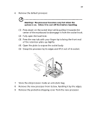
(4)
Lay down the HSF in an upright position—with the thermal
patch facing upward.
Do not let the thermal patch touch the
work surface.
5
Use an alcohol pad to wipe off the thermal grease from both the
HSF assembly and the processor socket retention plate.