Acer G330 User Manual - Page 59
Memory channel, DIMM slot, Population order, Interleave, Channel A, Total, memory, DIMM1A
 |
UPC - 750519177044
View all Acer G330 manuals
Add to My Manuals
Save this manual to your list of manuals |
Page 59 highlights
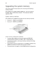
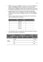
41 • DIMMs on channel A (DIMM1A and 2A) are paired with DIMMs on channel B (DIMM1B and 2B) to enable two-way interleaving. When only two DIMMs are being used, the population order must be DIMM1A and DIMM1B to ensure dual-channel operating mode. • For best performance and dual-channel interleave operation, DIMM modules must be installed or removed in matched pairs, following the slot sequence: DIMM1A and 1B first, then DIMM2A and 2B. • Observe the population sequence illustrated in the table below when installing a memory module. Memory channel A A B B DIMM slot DIMM1A DIMM2A DIMM1B DIMM2B Population order 1 3 2 4 • The table below lists the supported memory installation based on the memory interleave configuration. Interleave mode Channel A DIMM1A DIMM2A Channel B DIMM1B DIMM2B Total memory Single channel 512 MB 1 GB 2 GB 512 MB 1 GB 2 GB
-
 1
1 -
2
-
3
-
4
-
5
-
6
-
7
-
8
-
9
-
10
-
11
-
12
-
13
-
14
-
15
-
16
-
17
-
18
-
19
-
20
-
21
-
22
-
23
-
24
-
25
-
26
-
27
-
28
-
29
-
30
-
31
-
32
-
33
-
34
-
35
-
36
-
37
-
38
-
39
-
40
-
41
-
42
-
43
-
44
-
45
-
46
-
47
-
48
-
49
-
50
-
51
-
52
-
53
-
 54
54 -
 55
55 -
 56
56 -
 57
57 -
 58
58 -
 59
59 -
 60
60 -
 61
61 -
 62
62 -
 63
63 -
 64
64 -
65
-
66
-
67
-
68
-
69
-
70
-
71
-
72
-
73
-
74
-
75
-
76
-
77
-
78
-
79
-
80
-
81
-
82
-
83
-
84
-
85
-
86
-
87
-
88
-
89
-
90
-
91
-
92
-
93
-
94
-
95
-
96
-
97
-
98
-
99
-
100
-
101
-
102
-
103
-
104
-
105
-
106
-
107
-
108
-
109
-
110
-
111
-
112
-
113
-
114
-
115
-
116
-
117
-
118
-
119
-
120
-
121
-
122
-
123
-
124
-
125
-
126
-
127
-
128
-
129
-
130
-
131
-
132
-
133
-
134
 |
 |
