Acer G330 User Manual - Page 56
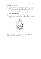
Apply a thin layer of an Acer-approved thermal interface material
 |
UPC - 750519177044
View all Acer G330 manuals
Add to My Manuals
Save this manual to your list of manuals |
Page 56 highlights
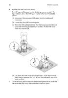
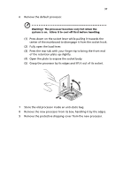
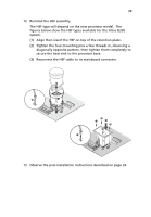
38 3 System upgrade 10 Install the new processor. (1) Hold the processor by its edges, then insert it in the socket. Make sure that the alignment tabs on the socket fit the two notches located on the edge of the processor. The pins are keyed in such a way that you cannot install the processor in the wrong orientation without bending the pins. (2) Close the retention plate. (3) Press down on the socket lever while pushing it towards the center of the processor socket to engage it under the socket hook. 11 Apply a thin layer of an Acer-approved thermal interface material to the processor base and the bottom side of the HSF. Make sure that only a very thin layer is applied so that both contact surfaces are still visible.
-
 1
1 -
2
-
3
-
4
-
5
-
6
-
7
-
8
-
9
-
10
-
11
-
12
-
13
-
14
-
15
-
16
-
17
-
18
-
19
-
20
-
21
-
22
-
23
-
24
-
25
-
26
-
27
-
28
-
29
-
30
-
31
-
32
-
33
-
34
-
35
-
36
-
37
-
38
-
39
-
40
-
41
-
42
-
43
-
44
-
45
-
46
-
47
-
48
-
49
-
50
-
 51
51 -
 52
52 -
 53
53 -
 54
54 -
 55
55 -
 56
56 -
 57
57 -
 58
58 -
 59
59 -
 60
60 -
 61
61 -
62
-
63
-
64
-
65
-
66
-
67
-
68
-
69
-
70
-
71
-
72
-
73
-
74
-
75
-
76
-
77
-
78
-
79
-
80
-
81
-
82
-
83
-
84
-
85
-
86
-
87
-
88
-
89
-
90
-
91
-
92
-
93
-
94
-
95
-
96
-
97
-
98
-
99
-
100
-
101
-
102
-
103
-
104
-
105
-
106
-
107
-
108
-
109
-
110
-
111
-
112
-
113
-
114
-
115
-
116
-
117
-
118
-
119
-
120
-
121
-
122
-
123
-
124
-
125
-
126
-
127
-
128
-
129
-
130
-
131
-
132
-
133
-
134
 |
 |
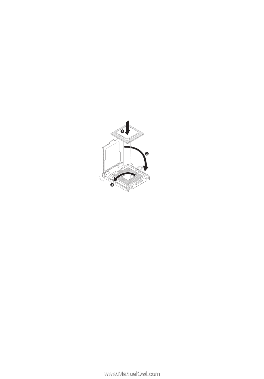
3 System upgrade
38
10
Install the new processor.
(1)
Hold the processor by its edges, then insert it in the socket.
Make sure that the alignment tabs on the socket fit the two
notches located on the edge of the processor.
The pins are
keyed in such a way that you cannot install the processor in
the wrong orientation without bending the pins.
(2)
Close the retention plate.
(3)
Press down on the socket lever while pushing it towards the
center of the processor socket to engage it under the socket
hook.
11
Apply a thin layer of an Acer-approved thermal interface material
to the processor base and the bottom side of the HSF.
Make sure that only a
very thin layer
is applied so that both
contact surfaces are still visible.