Alcatel OS6855-24 User Guide - Page 71
Final Power Cord Connections, Output Power Terminal Locations North America wire color shown, Caution.
 |
View all Alcatel OS6855-24 manuals
Add to My Manuals
Save this manual to your list of manuals |
Page 71 highlights
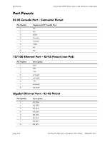
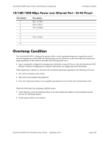
OmniSwitch 6855 Series Chassis and Hardware Components Installing the PS-I185AC-P (SDR-240-55) Power Supply 5 To secure the standard portion of the "Y-type" or straight AC power cord, begin by inserting the BLACK (North America) or BROWN (International) wire into the Line (L) terminal located at the bottom-front of the PoE power supply. 6 Next, insert the WHITE (North America) or BLUE (International) wire into the Neutral (N) terminal. 7 Insert the GREEN (North America) or GREEN/YELLOW stripe (International) ground wire into the terminal marked with the protective ground symbol. N L Bottom-Front of Power Supply Output Power Terminal Locations (North America wire color shown) 8 Using a screwdriver torque each terminal to 7 inch-pounds. 9 Secure the power supply by referring to "PS-I185AC-P (SDR-240-55) Power Supply Mounting" on page 4-14 Final Power Cord Connections 1 Once the power supply has been secured to the tray, insert the output power cord's four pin connector into the PoE power port located on the rear panel of the OS6855-P14 chassis. 2 Plug the AC power cord's IEC 60320 C15 connector into the switch's system power supply brick. 3 Plug the AC power cord's NEMA 5-15 into an easily accessible AC power source. Caution. The product uses a Pluggable Type A power cord; therefore, please make sure that the power socket is located near the equipment and is easily accessible. OmniSwitch 6855 Series Hardware Users Guide September 2011 page 2-49
-
 1
1 -
2
-
3
-
4
-
5
-
6
-
7
-
8
-
9
-
10
-
11
-
12
-
13
-
14
-
15
-
16
-
17
-
18
-
19
-
20
-
21
-
22
-
23
-
24
-
25
-
26
-
27
-
28
-
29
-
30
-
31
-
32
-
33
-
34
-
35
-
36
-
37
-
38
-
39
-
40
-
41
-
42
-
43
-
44
-
45
-
46
-
47
-
48
-
49
-
50
-
51
-
52
-
53
-
54
-
55
-
56
-
57
-
58
-
59
-
60
-
61
-
62
-
63
-
64
-
65
-
 66
66 -
 67
67 -
 68
68 -
 69
69 -
 70
70 -
 71
71 -
 72
72 -
 73
73 -
 74
74 -
 75
75 -
 76
76 -
77
-
78
-
79
-
80
-
81
-
82
-
83
-
84
-
85
-
86
-
87
-
88
-
89
-
90
-
91
-
92
-
93
-
94
-
95
-
96
-
97
-
98
-
99
-
100
-
101
-
102
-
103
-
104
-
105
-
106
-
107
-
108
-
109
-
110
-
111
-
112
-
113
-
114
-
115
-
116
-
117
-
118
-
119
-
120
-
121
-
122
-
123
-
124
-
125
-
126
-
127
-
128
-
129
-
130
-
131
-
132
-
133
-
134
-
135
-
136
-
137
-
138
-
139
-
140
-
141
-
142
-
143
-
144
-
145
-
146
-
147
-
148
-
149
-
150
-
151
-
152
-
153
-
154
-
155
-
156
-
157
-
158
-
159
-
160
-
161
-
162
-
163
-
164
-
165
-
166
-
167
-
168
-
169
-
170
-
171
-
172
-
173
-
174
-
175
-
176
-
177
-
178
-
179
-
180
-
181
-
182
-
183
-
184
-
185
-
186
-
187
-
188
-
189
-
190
-
191
-
192
-
193
-
194
-
195
-
196
-
197
-
198
-
199
-
200
-
201
-
202
-
203
-
204
 |
 |
