Alcatel OS6855-24 User Guide - Page 77
Mounting OS6855-24 and OS6855-U24/U24X, General Mounting Recommendations, Recommended Clearances
 |
View all Alcatel OS6855-24 manuals
Add to My Manuals
Save this manual to your list of manuals |
Page 77 highlights
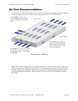
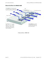
3 Mounting OS6855-24 and OS6855-U24/U24X Note. Never obstruct the air intake or exhaust vents located on the chassis. Obstructing these vents can cause switch failure. Always follow the recommended clearance values. General Mounting Recommendations Be sure that your switch is placed in a well-ventilated, static-free environment. Always allow adequate clearance at the front, rear, top, and sides of the switch. Refer the the table below for detailed information on recommended chassis clearances. Recommended Clearances Always allow adequate clearance at the front, rear, top, and sides of the switch. The following table shows the recommended minimum clearances for adequate chassis air flow and access to cabling and components at the front and rear of the chassis. Location Top Bottom Sides Rear Front OS6855-24 No minimum clearance required. However, be sure that the top of the chassis is not in direct contact with any equipment above. No minimum clearance required. However, be sure that the bottom of the chassis is not in direct contact with any equipment below. 2 inches 6 inches (see note below) 6 inches (see note below) OS6855-U24/U24X 0.875 inches (1/2 RU) No minimum clearance required. However, be sure that the bottom of the chassis is not in direct contact with any equipment below. 2 inches 6 inches (see note below) 6 inches (see note below) Note. Clearance recommendations at the front and rear of chassis are for access to cabling and components only and are not intended as a specific air flow requirement. OmniSwitch 6855 Series Hardware Users Guide September 2011 page 3-1
-
 1
1 -
2
-
3
-
4
-
5
-
6
-
7
-
8
-
9
-
10
-
11
-
12
-
13
-
14
-
15
-
16
-
17
-
18
-
19
-
20
-
21
-
22
-
23
-
24
-
25
-
26
-
27
-
28
-
29
-
30
-
31
-
32
-
33
-
34
-
35
-
36
-
37
-
38
-
39
-
40
-
41
-
42
-
43
-
44
-
45
-
46
-
47
-
48
-
49
-
50
-
51
-
52
-
53
-
54
-
55
-
56
-
57
-
58
-
59
-
60
-
61
-
62
-
63
-
64
-
65
-
66
-
67
-
68
-
69
-
70
-
71
-
 72
72 -
 73
73 -
 74
74 -
 75
75 -
 76
76 -
 77
77 -
 78
78 -
 79
79 -
 80
80 -
 81
81 -
 82
82 -
83
-
84
-
85
-
86
-
87
-
88
-
89
-
90
-
91
-
92
-
93
-
94
-
95
-
96
-
97
-
98
-
99
-
100
-
101
-
102
-
103
-
104
-
105
-
106
-
107
-
108
-
109
-
110
-
111
-
112
-
113
-
114
-
115
-
116
-
117
-
118
-
119
-
120
-
121
-
122
-
123
-
124
-
125
-
126
-
127
-
128
-
129
-
130
-
131
-
132
-
133
-
134
-
135
-
136
-
137
-
138
-
139
-
140
-
141
-
142
-
143
-
144
-
145
-
146
-
147
-
148
-
149
-
150
-
151
-
152
-
153
-
154
-
155
-
156
-
157
-
158
-
159
-
160
-
161
-
162
-
163
-
164
-
165
-
166
-
167
-
168
-
169
-
170
-
171
-
172
-
173
-
174
-
175
-
176
-
177
-
178
-
179
-
180
-
181
-
182
-
183
-
184
-
185
-
186
-
187
-
188
-
189
-
190
-
191
-
192
-
193
-
194
-
195
-
196
-
197
-
198
-
199
-
200
-
201
-
202
-
203
-
204
 |
 |
