Alcatel OS6855-24 User Guide - Page 75
/100/1000 Mbps Power over Ethernet Port - RJ-45 Pinout, Overtemp Condition
 |
View all Alcatel OS6855-24 manuals
Add to My Manuals
Save this manual to your list of manuals |
Page 75 highlights
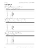
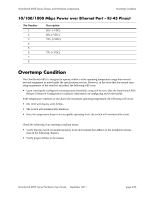
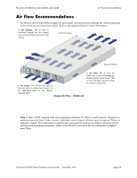
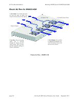
OmniSwitch 6855 Series Chassis and Hardware Components Overtemp Condition 10/100/1000 Mbps Power over Ethernet Port - RJ-45 Pinout Pin Number 1 2 3 4 5 6 7 8 Description RX+ (-VDC) RX- (-VDC) TX+ (+VDC) TX- (+VDC) Overtemp Condition The OmniSwitch 6855 is designed to operate within a wider operating temperature range than normal network equipment as noted under the specifications section. However, in the event that the normal operating temperature of the switch is exceeded, the following will occur: • Upon crossing the configured overtemperature threshold, a trap will be sent. (See the OmniSwitch AOS Release 6 Network Configuration Guide) for information on configuring switch thresholds. If the temperature continues to rise above the maximum operating temperature, the following will occur: • OK LED will display solid Amber. • The switch will automatically shutdown • Once the temperature drops to an acceptable operating level, the switch will automatically restart. Check the following if an overtemp condition exists: • Verify that the switch is installed properly in an environment that adheres to the installation instructions in the following chapters. • Verify proper airflow to the chassis. OmniSwitch 6855 Series Hardware Users Guide September 2011 page 2-53
-
 1
1 -
2
-
3
-
4
-
5
-
6
-
7
-
8
-
9
-
10
-
11
-
12
-
13
-
14
-
15
-
16
-
17
-
18
-
19
-
20
-
21
-
22
-
23
-
24
-
25
-
26
-
27
-
28
-
29
-
30
-
31
-
32
-
33
-
34
-
35
-
36
-
37
-
38
-
39
-
40
-
41
-
42
-
43
-
44
-
45
-
46
-
47
-
48
-
49
-
50
-
51
-
52
-
53
-
54
-
55
-
56
-
57
-
58
-
59
-
60
-
61
-
62
-
63
-
64
-
65
-
66
-
67
-
68
-
69
-
 70
70 -
 71
71 -
 72
72 -
 73
73 -
 74
74 -
 75
75 -
 76
76 -
 77
77 -
 78
78 -
 79
79 -
 80
80 -
81
-
82
-
83
-
84
-
85
-
86
-
87
-
88
-
89
-
90
-
91
-
92
-
93
-
94
-
95
-
96
-
97
-
98
-
99
-
100
-
101
-
102
-
103
-
104
-
105
-
106
-
107
-
108
-
109
-
110
-
111
-
112
-
113
-
114
-
115
-
116
-
117
-
118
-
119
-
120
-
121
-
122
-
123
-
124
-
125
-
126
-
127
-
128
-
129
-
130
-
131
-
132
-
133
-
134
-
135
-
136
-
137
-
138
-
139
-
140
-
141
-
142
-
143
-
144
-
145
-
146
-
147
-
148
-
149
-
150
-
151
-
152
-
153
-
154
-
155
-
156
-
157
-
158
-
159
-
160
-
161
-
162
-
163
-
164
-
165
-
166
-
167
-
168
-
169
-
170
-
171
-
172
-
173
-
174
-
175
-
176
-
177
-
178
-
179
-
180
-
181
-
182
-
183
-
184
-
185
-
186
-
187
-
188
-
189
-
190
-
191
-
192
-
193
-
194
-
195
-
196
-
197
-
198
-
199
-
200
-
201
-
202
-
203
-
204
 |
 |
