Asus P I-P55SP3AV P/I-P55SP3AV User's manual - Page 12
Asus P I-P55SP3AV Manual
 |
View all Asus P I-P55SP3AV manuals
Add to My Manuals
Save this manual to your list of manuals |
Page 12 highlights
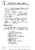
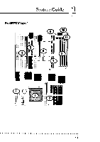
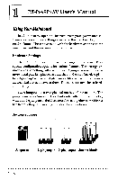
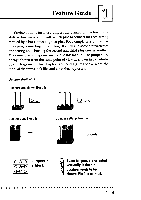
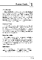
Feature Guide Setting options for most jumpers are printed on the board in a stylized bird's-eye view, with which pins to connect for each setting marked by a bar connecting two pins. For example, if a jumper has three pins, connecting, or 'shorting', the first and second pins creates one setting and shorting the second and third pins creates another. The same type of diagrams are used in this manual. The jumpers are always shown from the same point of view as shown in the wholeboard diagram in this chapter. The next figures show what the manual diagrams look like and what they represent. Jumper diagrams Jumpers are shown like this 0 0 00 000 Jumper caps like this Jumper settings like this O 0-0 O 0-0 O0-0 0-0 O Jumpers in a 'block' Some jumpers are oriented vertically; if the pin position needs to be O shown, Pin 1 is marked. 1 - 9
-
 1
1 -
2
-
3
-
4
-
5
-
6
-
 7
7 -
 8
8 -
 9
9 -
 10
10 -
 11
11 -
 12
12 -
 13
13 -
 14
14 -
 15
15 -
 16
16 -
 17
17 -
18
-
19
-
20
-
21
-
22
-
23
-
24
-
25
-
26
-
27
-
28
-
29
-
30
-
31
-
32
-
33
-
34
-
35
-
36
-
37
-
38
-
39
-
40
-
41
-
42
-
43
-
44
-
45
-
46
-
47
-
48
-
49
-
50
-
51
-
52
-
53
-
54
-
55
-
56
-
57
-
58
-
59
-
60
-
61
-
62
-
63
-
64
-
65
-
66
-
67
-
68
-
69
-
70
-
71
-
72
-
73
-
74
-
75
-
76
-
77
-
78
-
79
-
80
-
81
-
82
 |
 |
