Asus P I-P55SP3AV P/I-P55SP3AV User's manual - Page 77
Asus P I-P55SP3AV Manual
 |
View all Asus P I-P55SP3AV manuals
Add to My Manuals
Save this manual to your list of manuals |
Page 77 highlights
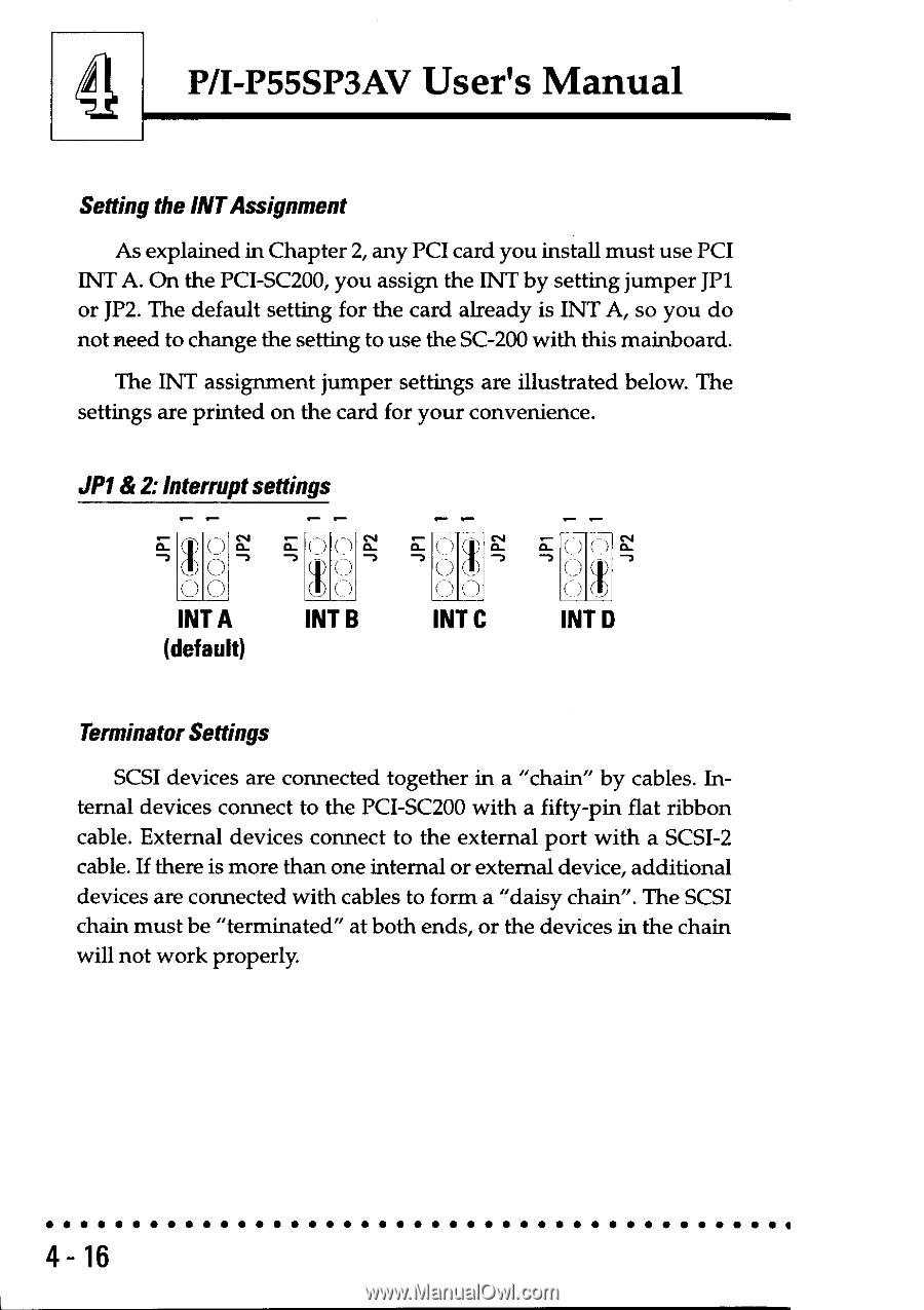
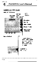
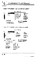
4 P/I-P55SP3AV User's Manual Setting the INT Assignment As explained in Chapter 2, any PCI card you install must use PCI INT A. On the PCI-SC200, you assign the INT by setting jumper JP1 or JP2. The default setting for the card already is INT A, so you do not need to change the setting to use the SC-200 with this mainboard. The INT assignment jumper settings are illustrated below. The settings are printed on the card for your convenience. JP1& 2:Interrupt settings (/ ) INT A (default) I I ( ) ) ( ) INT B E' ( ) ) a (_) 0 (7) INT C • • a ) ( () INT D Terminator Settings SCSI devices are connected together in a "chain" by cables. Internal devices connect to the PCI-SC200 with a fifty-pin flat ribbon cable. External devices connect to the external port with a SCSI-2 cable. If there is more than one internal or external device, additional devices are connected with cables to form a "daisy chain". The SCSI chain must be "terminated" at both ends, or the devices in the chain will not work properly. 4- 16
-
 1
1 -
2
-
3
-
4
-
5
-
6
-
7
-
8
-
9
-
10
-
11
-
12
-
13
-
14
-
15
-
16
-
17
-
18
-
19
-
20
-
21
-
22
-
23
-
24
-
25
-
26
-
27
-
28
-
29
-
30
-
31
-
32
-
33
-
34
-
35
-
36
-
37
-
38
-
39
-
40
-
41
-
42
-
43
-
44
-
45
-
46
-
47
-
48
-
49
-
50
-
51
-
52
-
53
-
54
-
55
-
56
-
57
-
58
-
59
-
60
-
61
-
62
-
63
-
64
-
65
-
66
-
67
-
68
-
69
-
70
-
71
-
 72
72 -
 73
73 -
 74
74 -
 75
75 -
 76
76 -
 77
77 -
 78
78 -
 79
79 -
 80
80 -
 81
81 -
 82
82
 |
 |