Asus P I-P55SP3AV P/I-P55SP3AV User's manual - Page 73
Asus P I-P55SP3AV Manual
 |
View all Asus P I-P55SP3AV manuals
Add to My Manuals
Save this manual to your list of manuals |
Page 73 highlights
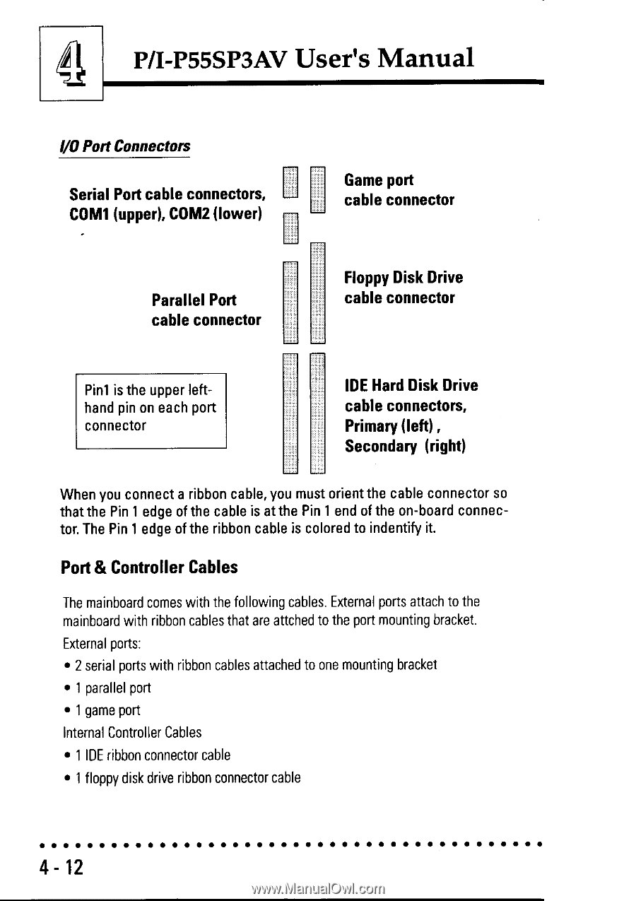
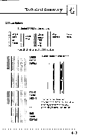
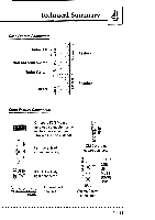
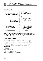
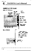
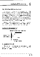
4 P/I-P55SP3AV User's Manual I/O Port Connectors Serial Port cable connectors, COM1 (upper), COM2 (lower) Game port cable connector Parallel Port cable connector Floppy Disk Drive cable connector Pin1 is the upper lefthand pin on each port connector IDE Hard Disk Drive cable connectors, Primary (left) , Secondary (right) When you connect a ribbon cable, you must orient the cable connector so that the Pin 1 edge of the cable is at the Pin 1 end of the on-board connector. The Pin 1 edge of the ribbon cable is colored to indentify it. Port & Controller Cables The mainboard comes with the following cables. External ports attach to the ma inboard with ribbon cables that are attched to the port mounting bracket. External ports: • 2 serial ports with ribbon cables attached to one mounting bracket • 1 parallel port • 1 game port Internal Controller Cables • 1 IDE ribbon connector cable • 1 floppy disk drive ribbon connector cable 4- 12
-
 1
1 -
2
-
3
-
4
-
5
-
6
-
7
-
8
-
9
-
10
-
11
-
12
-
13
-
14
-
15
-
16
-
17
-
18
-
19
-
20
-
21
-
22
-
23
-
24
-
25
-
26
-
27
-
28
-
29
-
30
-
31
-
32
-
33
-
34
-
35
-
36
-
37
-
38
-
39
-
40
-
41
-
42
-
43
-
44
-
45
-
46
-
47
-
48
-
49
-
50
-
51
-
52
-
53
-
54
-
55
-
56
-
57
-
58
-
59
-
60
-
61
-
62
-
63
-
64
-
65
-
66
-
67
-
 68
68 -
 69
69 -
 70
70 -
 71
71 -
 72
72 -
 73
73 -
 74
74 -
 75
75 -
 76
76 -
 77
77 -
 78
78 -
79
-
80
-
81
-
82
 |
 |