Asus P I-P55SP3AV P/I-P55SP3AV User's manual - Page 74
Asus P I-P55SP3AV Manual
 |
View all Asus P I-P55SP3AV manuals
Add to My Manuals
Save this manual to your list of manuals |
Page 74 highlights
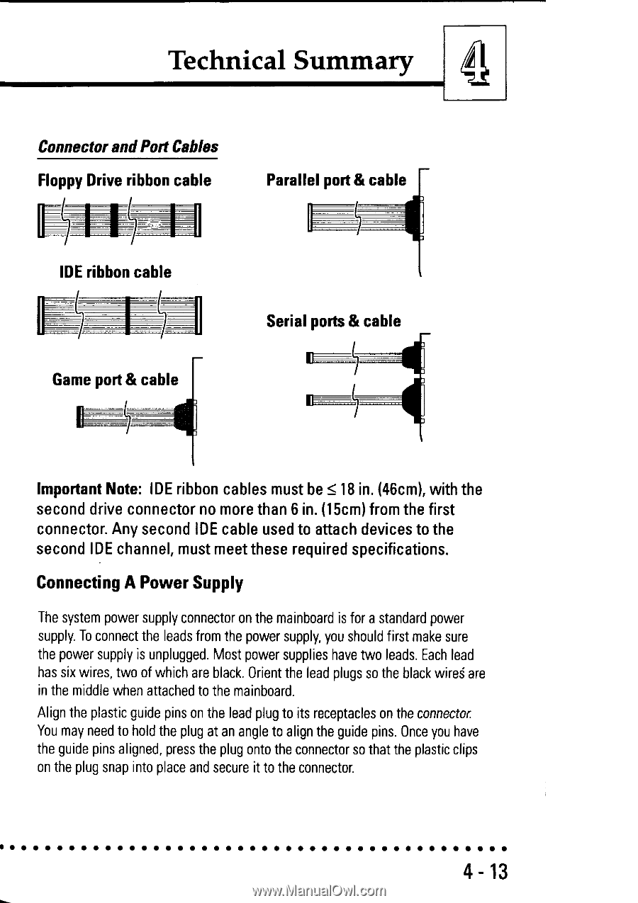
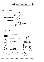
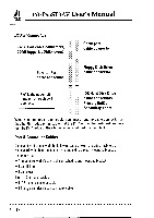
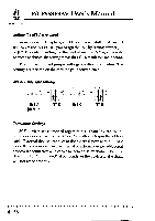
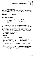
4 Technical Summary Connector andPort Cables Floppy Drive ribbon cable IDE ribbon cable Game port & cable Parallel port & cable H Serial ports & cable Ii. Important Note: IDE ribbon cables must be ≤ 18 in. (46cm), with the second drive connector no more than 6 in. (15cm) from the first connector. Any second IDE cable used to attach devices to the second IDE channel, must meet these required specifications. Connecting A Power Supply The system power supply connector on the mainboard is for a standard power supply. To connect the leads from the power supply, you should first make sure the power supply is unplugged. Most power supplies have two leads. Each lead has six wires, two of which are black. Orient the lead plugs so the black wires are in the middle when attached to the mainboard. Align the plastic guide pins on the lead plug to its receptacles on the connector. You may need to hold the plug at an angle to align the guide pins. Once you have the guide pins aligned, press the plug onto the connector so that the plastic clips on the plug snap into place and secure it to the connector. 4-13
-
 1
1 -
2
-
3
-
4
-
5
-
6
-
7
-
8
-
9
-
10
-
11
-
12
-
13
-
14
-
15
-
16
-
17
-
18
-
19
-
20
-
21
-
22
-
23
-
24
-
25
-
26
-
27
-
28
-
29
-
30
-
31
-
32
-
33
-
34
-
35
-
36
-
37
-
38
-
39
-
40
-
41
-
42
-
43
-
44
-
45
-
46
-
47
-
48
-
49
-
50
-
51
-
52
-
53
-
54
-
55
-
56
-
57
-
58
-
59
-
60
-
61
-
62
-
63
-
64
-
65
-
66
-
67
-
68
-
 69
69 -
 70
70 -
 71
71 -
 72
72 -
 73
73 -
 74
74 -
 75
75 -
 76
76 -
 77
77 -
 78
78 -
 79
79 -
80
-
81
-
82
 |
 |