Bosch DVR-16L-100A Operation Manual - Page 15
Back panel - relay
 |
View all Bosch DVR-16L-100A manuals
Add to My Manuals
Save this manual to your list of manuals |
Page 15 highlights
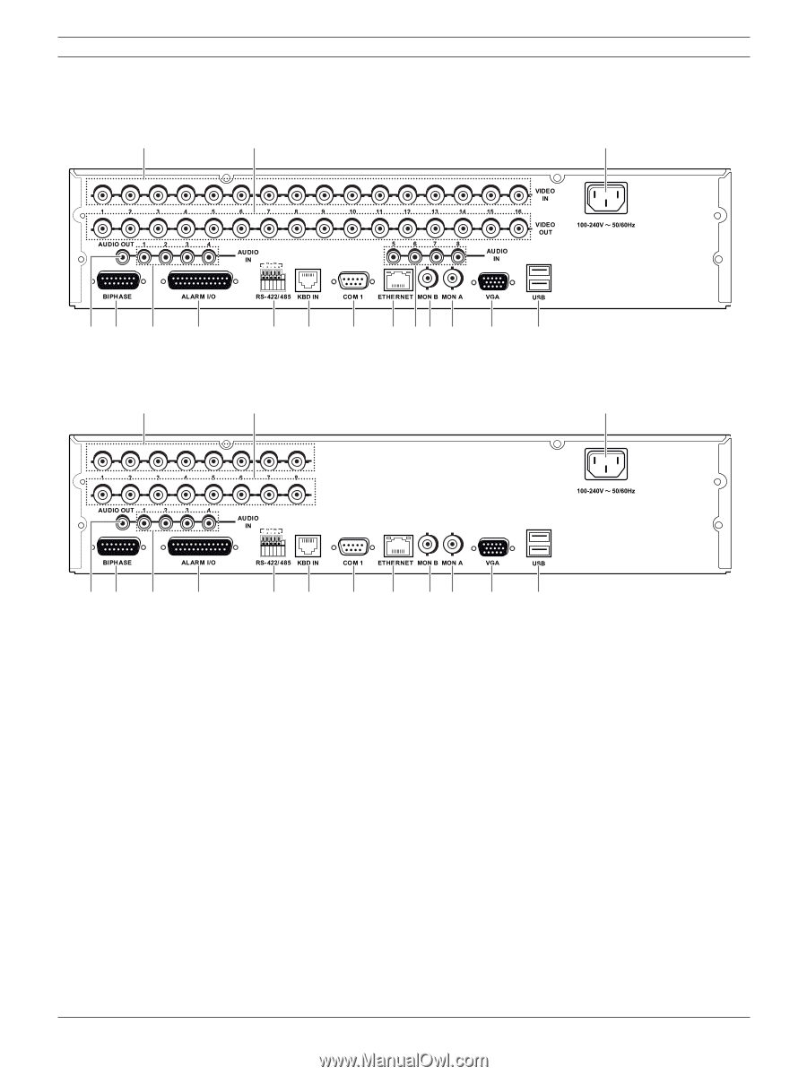
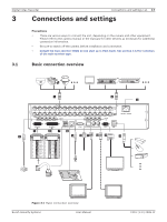
Digital Video Recorder 2.4 Back panel DVR-16K / DVR-16L a b Introduction | en 13 c de f g h i j k fl m n o DVR-8K / DVR-8L a b c de f g h i j k lm n o Figure 2.3 Back panel a VIDEO INPUT: Connect the camera's video output to these BNC connectors. b LOOP OUT: The signal from VIDEO INPUT connector is looped out to this connector. c Power Cord Inlet (AC IN): Connect the power plug. d AUDIO OUT: Connect the audio input signal of an external device. e BIPHASE: Connect a pan/tilt/zoom control unit via the supplied 15-pole D-type connector board. f AUDIO IN: Connect the audio output of an external device. g ALARM I/O: Connect up to 16 alarm inputs via the supplied 25-pin D-type connector board. Connect up to 8 alarm output relays via the supplied 25-pin D-type connector board. h RS-422/485 Terminals: Connect RS422/485 compatible cameras. i KBD IN: Connect a Bosch CCTV keyboard unit to the KBD IN socket. j COM1: Use to connect to a host device equipped with RS-232C connector (such as a personal computer). k ETHERNET Port: Connect the ethernet 10/100Mbps network cable for controlling this unit via a PC network. l MON B (BNC Type Connector): Connect to spot monitor or display device. Bosch Security Systems User Manual F01U | 2.0 | 2008.12
-
 1
1 -
2
-
3
-
4
-
5
-
6
-
7
-
8
-
9
-
 10
10 -
 11
11 -
 12
12 -
 13
13 -
 14
14 -
 15
15 -
 16
16 -
 17
17 -
 18
18 -
 19
19 -
 20
20 -
21
-
22
-
23
-
24
-
25
-
26
-
27
-
28
-
29
-
30
-
31
-
32
-
33
-
34
-
35
-
36
-
37
-
38
-
39
-
40
-
41
-
42
-
43
-
44
-
45
-
46
-
47
-
48
-
49
-
50
-
51
-
52
-
53
-
54
-
55
-
56
-
57
-
58
-
59
-
60
-
61
-
62
-
63
-
64
-
65
-
66
-
67
-
68
-
69
-
70
-
71
-
72
-
73
-
74
-
75
-
76
-
77
-
78
-
79
-
80
-
81
-
82
-
83
-
84
-
85
-
86
-
87
-
88
-
89
-
90
-
91
-
92
-
93
-
94
-
95
-
96
-
97
-
98
-
99
-
100
-
101
-
102
-
103
-
104
-
105
-
106
-
107
-
108
-
109
-
110
-
111
-
112
-
113
-
114
-
115
-
116
-
117
-
118
-
119
-
120
-
121
-
122
-
123
-
124
-
125
-
126
-
127
-
128
-
129
-
130
-
131
-
132
-
133
-
134
-
135
-
136
-
137
-
138
-
139
-
140
 |
 |