Bosch DVR-16L-100A Operation Manual - Page 28
System Control Bar
 |
View all Bosch DVR-16L-100A manuals
Add to My Manuals
Save this manual to your list of manuals |
Page 28 highlights
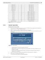
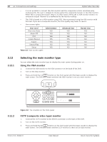
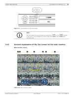
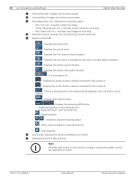
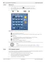
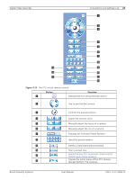
26 en | Connections and settings Digital Video Recorder a Channel Number: Displays the channel number. b Camera Name: Displays the edited camera name. c Recording status icon: Displays the recording status. • Red "Dot icon" indicates Instant recording. • Yellow "Running man icon" indicates motion detection recording. • Red "Alarm bell icon" indicates input triggered recording. d Selected Channel: Displays the selected channel with yellow box. e System Control Bar • : Displays the setup menu. • : Displays the search menu. • : Displays the PTZ remote control window. • : Displays the lock menu to change the user type or disable system operation. • : Displays the system log list window. • : Displays the system information window. • : Turns the alarm off. • : Displays the screen division selection window for the monitor A. • : Displays the screen division selection window for the monitor B. • : Click at a desired point to be marked during playback. Up to 15 points can be marked. • : Display copy (export) menu. • :Displays the remaining HDD status. - N (Normal partition): Used size/total size. - E (Event partition): Used size/total size. • : Pause playback. • : Select the required scanning speed. • : Starts instant playback in selected channel. • : Stop playback. f Live Screen: Displays the current surveillance live screen. g Displays the current date and time. Note: Click the right button on the mouse to display / remove the system control bar displayed on-screen. F01U | 2.0 | 2008.12 User Manual Bosch Security Systems
-
 1
1 -
2
-
3
-
4
-
5
-
6
-
7
-
8
-
9
-
10
-
11
-
12
-
13
-
14
-
15
-
16
-
17
-
18
-
19
-
20
-
21
-
22
-
 23
23 -
 24
24 -
 25
25 -
 26
26 -
 27
27 -
 28
28 -
 29
29 -
 30
30 -
 31
31 -
 32
32 -
 33
33 -
34
-
35
-
36
-
37
-
38
-
39
-
40
-
41
-
42
-
43
-
44
-
45
-
46
-
47
-
48
-
49
-
50
-
51
-
52
-
53
-
54
-
55
-
56
-
57
-
58
-
59
-
60
-
61
-
62
-
63
-
64
-
65
-
66
-
67
-
68
-
69
-
70
-
71
-
72
-
73
-
74
-
75
-
76
-
77
-
78
-
79
-
80
-
81
-
82
-
83
-
84
-
85
-
86
-
87
-
88
-
89
-
90
-
91
-
92
-
93
-
94
-
95
-
96
-
97
-
98
-
99
-
100
-
101
-
102
-
103
-
104
-
105
-
106
-
107
-
108
-
109
-
110
-
111
-
112
-
113
-
114
-
115
-
116
-
117
-
118
-
119
-
120
-
121
-
122
-
123
-
124
-
125
-
126
-
127
-
128
-
129
-
130
-
131
-
132
-
133
-
134
-
135
-
136
-
137
-
138
-
139
-
140
 |
 |
