Brother International BES-100E BE-100 Workbook - English - Page 96
BE-100 terms
 |
View all Brother International BES-100E manuals
Add to My Manuals
Save this manual to your list of manuals |
Page 96 highlights
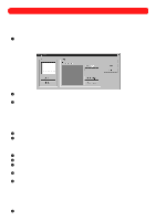
q Zoom tool ( ) Used to zoom in precisely on an area by dragging the pointer over the desired area until it is enclosed in the zoom selection box. s BE-100 terms q Background image (Image group box on Background dialog box) Allows a scanned image to be displayed in the background so the sewing area can be visualized or an image can be traced. For example, the back of a cap can be scanned and used as a background image to easily create lettering that matches the arch of the cap. q Border group box (Column tab of BES Setup dialog box) Used to determine the default column border width. q Character width group box (Text Effects tab of Text Properties dialog box) Used to adjust the width of text. q Character kerning group box (Text Effects tab of Text Properties dialog box) Used to adjust the space between characters uniformly. q Clear (on Edit drop-down menu) Deletes or removes the selection. q Connect furthest points check box (Text tab of Text Properties dialog box) Used to rearrange start and stop points of text shapes so the jump stitch is as long as possible, making it easier to trim manually with scissors. Same as clicking the Connect Furthest button ( ) in the Text bar. q Connection group box (Commands tab of corresponding Properties dialog box) Used to determine how the selected design shape is connected to the next shape. q Crosshairs (on View drop-down menu) Turns on moveable crossed lines that span the screen and are controlled by the mouse. Used to check the alignment of design shapes. q Default corner correction group box (Column tab of BES Setup dialog box) Used to determine how angles in columns will be created. Depending on the degree of the angle and setting selected, the corner may be squared off, mitered, or angled. q Deconstruct Text (on Shape drop-down menu) Breaks text shapes into individual characters, allowing resizing, color and font changes, and placement of single letters. Same as clicking the Deconstruct Text button ( Text bar. ) in the q Density adjustment box (Stitches tab of corresponding Properties dialog box) Used to control the number of stitches in a given area. q Design Info (on File drop-down menu) Allows various custom settings for the current design to be specified. Applies only to the current design. Values return to default settings after current design is saved and/or closed. q Design Reference window Displays a thumbnail of the entire design. The area shown in the main window is indicated by the dotted lines. Drag the pointer over the desired area in the Design Reference window to zoom in on it. q Duplicate (on Edit drop-down menu) Makes a copy of the selection and pastes it into the design area. q Entry and exit points check box (Markers dialog box) Used to display small green dots, which indicate the first needle penetration of a shape, and red dots marking the exit point. 93
-
 1
1 -
2
-
3
-
4
-
5
-
6
-
7
-
8
-
9
-
10
-
11
-
12
-
13
-
14
-
15
-
16
-
17
-
18
-
19
-
20
-
21
-
22
-
23
-
24
-
25
-
26
-
27
-
28
-
29
-
30
-
31
-
32
-
33
-
34
-
35
-
36
-
37
-
38
-
39
-
40
-
41
-
42
-
43
-
44
-
45
-
46
-
47
-
48
-
49
-
50
-
51
-
52
-
53
-
54
-
55
-
56
-
57
-
58
-
59
-
60
-
61
-
62
-
63
-
64
-
65
-
66
-
67
-
68
-
69
-
70
-
71
-
72
-
73
-
74
-
75
-
76
-
77
-
78
-
79
-
80
-
81
-
82
-
83
-
84
-
85
-
86
-
87
-
88
-
89
-
90
-
 91
91 -
 92
92 -
 93
93 -
 94
94 -
 95
95 -
 96
96 -
 97
97 -
 98
98 -
 99
99 -
 100
100 -
 101
101 -
102
-
103
-
104
-
105
-
106
-
107
-
108
-
109
-
110
-
111
-
112
-
113
-
114
-
115
-
116
-
117
-
118
-
119
 |
 |
