Brother International FAX 275 Service Manual - Page 22
Clutch, Cutout, clutch, Stopper, Planet, Released, Motor, Solenoid, Front, Active, Gears, Drive,
 |
UPC - 012502564546
View all Brother International FAX 275 manuals
Add to My Manuals
Save this manual to your list of manuals |
Page 22 highlights
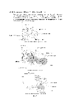
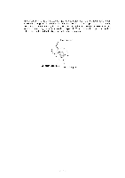
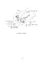
I 3 / Copying mode (Solenoid: ON-►OFF, Motor rotation: Forward) The control electronics at first activates the solenoid to release the stopper of arm A from the cutout ® of the clutch arm while rotating the motor in the forward direction. Accordingly, the sun gear 18/82 (B) rotates counterclockwise so that both the planet gears 20B (01) and 20A (02) transmit the rotation; Cl rotation to the platen gear (H) and C2 rotation to the separation roller gear (L) and white pressure roller gear (0). Once the planet gear 20A (02) becomes engaged with gear K, the control electronics deactivates the solenoid. O Clutch arm Cutout 0 of clutch arm -- 0 -f) Stopper of arm A C2 (Planet gear 20A) cO C1 (Planet gear 20B) B (Sun gear 18/82) Arm A Released from Cutout ® of Clutch Arm A (Motor gear) 0 o Al -- --,. „ C2 (Planet gear 20A) 0 Solenoid 0 0 (Front) C1 (Planet gear 20B) B (Sun gear 18/82) © 0 I 0 Active Gears on the Drive Unit 0 O ©fr---- D L (Separation roller gear) 0 0 O 0 O (White pressure roller gear) 0 © 0 O G 0 0 N H (Platen gear) --------- (Front) Active Gears on the Scanner Frame ASSY
-
 1
1 -
2
-
3
-
4
-
5
-
6
-
7
-
8
-
9
-
10
-
11
-
12
-
13
-
14
-
15
-
16
-
 17
17 -
 18
18 -
 19
19 -
 20
20 -
 21
21 -
 22
22 -
 23
23 -
 24
24 -
 25
25 -
 26
26 -
 27
27 -
28
-
29
-
30
-
31
-
32
-
33
-
34
-
35
-
36
-
37
-
38
-
39
-
40
-
41
-
42
-
43
-
44
-
45
-
46
-
47
-
48
-
49
-
50
-
51
-
52
-
53
-
54
-
55
-
56
-
57
-
58
-
59
-
60
-
61
-
62
-
63
-
64
-
65
-
66
-
67
-
68
-
69
-
70
-
71
-
72
-
73
-
74
-
75
-
76
-
77
-
78
-
79
-
80
-
81
-
82
-
83
-
84
-
85
-
86
-
87
-
88
-
89
-
90
-
91
-
92
-
93
-
94
-
95
-
96
-
97
-
98
-
99
-
100
-
101
-
102
-
103
-
104
-
105
-
106
-
107
-
108
-
109
-
110
-
111
-
112
-
113
-
114
-
115
-
116
-
117
-
118
-
119
-
120
-
121
-
122
-
123
-
124
-
125
-
126
-
127
-
128
-
129
-
130
-
131
-
132
-
133
-
134
-
135
-
136
-
137
-
138
-
139
-
140
-
141
-
142
-
143
-
144
-
145
-
146
-
147
-
148
-
149
-
150
-
151
-
152
-
153
-
154
-
155
-
156
-
157
-
158
-
159
-
160
-
161
-
162
-
163
-
164
-
165
-
166
-
167
-
168
-
169
-
170
-
171
-
172
-
173
-
174
-
175
-
176
-
177
-
178
-
179
-
180
-
181
-
182
-
183
-
184
-
185
-
186
-
187
-
188
-
189
-
190
-
191
-
192
-
193
-
194
-
195
-
196
-
197
-
198
-
199
-
200
-
201
-
202
-
203
-
204
-
205
-
206
-
207
-
208
-
209
-
210
-
211
-
212
-
213
-
214
-
215
-
216
-
217
-
218
-
219
-
220
-
221
-
222
-
223
-
224
-
225
-
226
-
227
-
228
-
229
-
230
-
231
-
232
-
233
-
234
-
235
-
236
-
237
-
238
-
239
-
240
-
241
-
242
-
243
-
244
-
245
-
246
-
247
-
248
-
249
-
250
-
251
-
252
-
253
-
254
-
255
-
256
-
257
-
258
-
259
-
260
-
261
-
262
-
263
-
264
-
265
-
266
-
267
 |
 |
