Brother International FAX 275 Service Manual - Page 26
Sensors, Actuators
 |
UPC - 012502564546
View all Brother International FAX 275 manuals
Add to My Manuals
Save this manual to your list of manuals |
Page 26 highlights
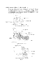
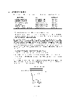
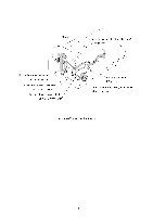
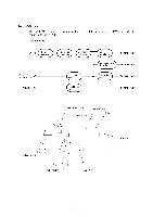
2.4 Sensors and Actuators This equipment has two photosensors and four mechanical switches as described below. Sensor name Document front sensor Document rear sensor Paper empty (PE) sensor Cover sensor Hook switch sensor Cutter home position (HP) sensor Type Photosensor (PHI) Photosensor (PH2) Mechanical switch (SW1) Mechanical switch (SW2) Mechanical switch (SW3) Mechanical switch Located on Main PCB Main PCB Main PCB Main PCB Main PCB Drive unit • Document front sensor which detects the presence of documents. • Document rear sensor which detects the leading and trailing edges of pages to tell the control circuitry when the leading edge of a new page has reached the starting position and when the scan for that page is over. These photosensors are of a reflection type consisting of a light-emitting diode and a lightsensitive transistor. Each of them has an actuator separately arranged (see the next page). When an actuator is not activated, its white end lies in the path of light issued from the lightemitting diode and reflects its light into the light-sensitive transistor. If a document is fed in so as to activate the actuator, the actuator's white end goes out of the light path. With no reflected light to go into the light-sensitive transistor, the sensor detects the presence of documents. • PE sensor which detects when the recording paper runs out. • Cover sensor which detects whether the control panel is closed. • Hook switch sensor which detects whether the handset is placed on the handset mount. • Cutter HP sensor which detects the home position of the upper rotary blade of the automatic cutter. Each of these four sensors has an actuator separately arranged (see the next page). If an actuator is activated, its lower end releases or pushes down the lever provided on the corresponding sensor so that the sensor signals the detection. Approx. 0.7 mm Path of actuator's end / \\ ,--- Glass i I. Light- Lightemitting sensitive diode transistor Photosensor III - 15
-
 1
1 -
2
-
3
-
4
-
5
-
6
-
7
-
8
-
9
-
10
-
11
-
12
-
13
-
14
-
15
-
16
-
17
-
18
-
19
-
20
-
 21
21 -
 22
22 -
 23
23 -
 24
24 -
 25
25 -
 26
26 -
 27
27 -
 28
28 -
 29
29 -
 30
30 -
 31
31 -
32
-
33
-
34
-
35
-
36
-
37
-
38
-
39
-
40
-
41
-
42
-
43
-
44
-
45
-
46
-
47
-
48
-
49
-
50
-
51
-
52
-
53
-
54
-
55
-
56
-
57
-
58
-
59
-
60
-
61
-
62
-
63
-
64
-
65
-
66
-
67
-
68
-
69
-
70
-
71
-
72
-
73
-
74
-
75
-
76
-
77
-
78
-
79
-
80
-
81
-
82
-
83
-
84
-
85
-
86
-
87
-
88
-
89
-
90
-
91
-
92
-
93
-
94
-
95
-
96
-
97
-
98
-
99
-
100
-
101
-
102
-
103
-
104
-
105
-
106
-
107
-
108
-
109
-
110
-
111
-
112
-
113
-
114
-
115
-
116
-
117
-
118
-
119
-
120
-
121
-
122
-
123
-
124
-
125
-
126
-
127
-
128
-
129
-
130
-
131
-
132
-
133
-
134
-
135
-
136
-
137
-
138
-
139
-
140
-
141
-
142
-
143
-
144
-
145
-
146
-
147
-
148
-
149
-
150
-
151
-
152
-
153
-
154
-
155
-
156
-
157
-
158
-
159
-
160
-
161
-
162
-
163
-
164
-
165
-
166
-
167
-
168
-
169
-
170
-
171
-
172
-
173
-
174
-
175
-
176
-
177
-
178
-
179
-
180
-
181
-
182
-
183
-
184
-
185
-
186
-
187
-
188
-
189
-
190
-
191
-
192
-
193
-
194
-
195
-
196
-
197
-
198
-
199
-
200
-
201
-
202
-
203
-
204
-
205
-
206
-
207
-
208
-
209
-
210
-
211
-
212
-
213
-
214
-
215
-
216
-
217
-
218
-
219
-
220
-
221
-
222
-
223
-
224
-
225
-
226
-
227
-
228
-
229
-
230
-
231
-
232
-
233
-
234
-
235
-
236
-
237
-
238
-
239
-
240
-
241
-
242
-
243
-
244
-
245
-
246
-
247
-
248
-
249
-
250
-
251
-
252
-
253
-
254
-
255
-
256
-
257
-
258
-
259
-
260
-
261
-
262
-
263
-
264
-
265
-
266
-
267
 |
 |
