Brother International FAX 275 Service Manual - Page 29
controlling
 |
UPC - 012502564546
View all Brother International FAX 275 manuals
Add to My Manuals
Save this manual to your list of manuals |
Page 29 highlights
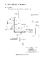
3.2 Main PCB The main PCB, which is the nucleus controlling the entire operation of the equipment, consists of a FAX engine (ASIC), memories, MODEM, motor drive circuitry, sensor detection circuitry, and analog circuits for scanning, recording, and power transmission shifting. 0 NCU Power supply 0 Speaker Mic** 0 0 0 Automatic cutter ROM E2PROM SRAM * DRAM ** FAX engine (ASIC) o Control panel a Recording head ciCIS Motor driver a Motor Sensors Ni-MH battery ** 00 PCI** E2PROM: Electrically Erasable Programmable Read-only Memory * Provided on the FAX255/FAX275/FAX-515/HOMEFAX3 ** Provided on the FAX355MC/FAX375MC/FAX-525DT/FAX-525MC Block Diagram of Main PCB III -18
-
 1
1 -
2
-
3
-
4
-
5
-
6
-
7
-
8
-
9
-
10
-
11
-
12
-
13
-
14
-
15
-
16
-
17
-
18
-
19
-
20
-
21
-
22
-
23
-
 24
24 -
 25
25 -
 26
26 -
 27
27 -
 28
28 -
 29
29 -
 30
30 -
 31
31 -
 32
32 -
 33
33 -
 34
34 -
35
-
36
-
37
-
38
-
39
-
40
-
41
-
42
-
43
-
44
-
45
-
46
-
47
-
48
-
49
-
50
-
51
-
52
-
53
-
54
-
55
-
56
-
57
-
58
-
59
-
60
-
61
-
62
-
63
-
64
-
65
-
66
-
67
-
68
-
69
-
70
-
71
-
72
-
73
-
74
-
75
-
76
-
77
-
78
-
79
-
80
-
81
-
82
-
83
-
84
-
85
-
86
-
87
-
88
-
89
-
90
-
91
-
92
-
93
-
94
-
95
-
96
-
97
-
98
-
99
-
100
-
101
-
102
-
103
-
104
-
105
-
106
-
107
-
108
-
109
-
110
-
111
-
112
-
113
-
114
-
115
-
116
-
117
-
118
-
119
-
120
-
121
-
122
-
123
-
124
-
125
-
126
-
127
-
128
-
129
-
130
-
131
-
132
-
133
-
134
-
135
-
136
-
137
-
138
-
139
-
140
-
141
-
142
-
143
-
144
-
145
-
146
-
147
-
148
-
149
-
150
-
151
-
152
-
153
-
154
-
155
-
156
-
157
-
158
-
159
-
160
-
161
-
162
-
163
-
164
-
165
-
166
-
167
-
168
-
169
-
170
-
171
-
172
-
173
-
174
-
175
-
176
-
177
-
178
-
179
-
180
-
181
-
182
-
183
-
184
-
185
-
186
-
187
-
188
-
189
-
190
-
191
-
192
-
193
-
194
-
195
-
196
-
197
-
198
-
199
-
200
-
201
-
202
-
203
-
204
-
205
-
206
-
207
-
208
-
209
-
210
-
211
-
212
-
213
-
214
-
215
-
216
-
217
-
218
-
219
-
220
-
221
-
222
-
223
-
224
-
225
-
226
-
227
-
228
-
229
-
230
-
231
-
232
-
233
-
234
-
235
-
236
-
237
-
238
-
239
-
240
-
241
-
242
-
243
-
244
-
245
-
246
-
247
-
248
-
249
-
250
-
251
-
252
-
253
-
254
-
255
-
256
-
257
-
258
-
259
-
260
-
261
-
262
-
263
-
264
-
265
-
266
-
267
 |
 |

3.2
Main
PCB
The
main
PCB,
which
is
the
nucleus
controlling
the
entire
operation
of
the
equipment,
con-
sists
of
a
FAX
engine
(ASIC),
memories,
MODEM,
motor
drive
circuitry,
sensor
detection
cir-
cuitry,
and
analog
circuits
for
scanning,
recording,
and
power
transmission
shifting.
NCU
Power
supply
Speaker
Mic**
Automatic
cutter
0
0
0
0
0
ROM
E
2
PROM
SRAM
*
DRAM
**
FAX
engine
(ASIC)
Motor
driver
Sensors
o
a
ci
a
0
0
Control
panel
Recording
head
CIS
Motor
Ni-MH
battery
**
PCI**
E
2
PROM:
Electrically
Erasable
Programmable
Read-only
Memory
*
Provided
on
the
FAX255/FAX275/FAX-515/HOMEFAX3
**
Provided
on
the
FAX355MC/FAX375MC/FAX-525DT/FAX-525MC
Block
Diagram
of
Main
PCB
III
-18