Brother International FAX 275 Service Manual - Page 34
Power, Supply
 |
UPC - 012502564546
View all Brother International FAX 275 manuals
Add to My Manuals
Save this manual to your list of manuals |
Page 34 highlights
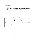
3.5 Power Supply PCB The power supply uses the switching regulation system to generate DC power (+26.6V and +8V) from a commercial AC power supply. The +26.6V source is stabilized and fed to the motor and solenoid for feeding documents and recording paper or activating the automatic cutter, and also fed to the CIS LED array. It is also fed to the main PCB where the H26.6V source is generated. The H26.6V source outputs 26.6V only when the H26.6V ON/OFF control signal is High, for driving the recording head. The +8V source is not stabilized and fed to the speaker. It is also fed to the main PCB where the 3-terminal regulator eliminates unstabilized components of the +8V source to generate stabilized +5V source. The +5V source is fed to the logic, control panel, and sensors. Commercial AC Power Line Fuse Lightning Surge Absorption Circuit Link Filter Rectifier Circuit v Oscillator Circuit Output Feedback 26.6 V Output Circuit 00000000000 8V Output Circuit Main PCB o H26.6V ON/OFF Control Signal H26.6V Output Circuit a H26.6V ° 26.6 V O 8 V Power Supply Circuit III - 23
-
 1
1 -
2
-
3
-
4
-
5
-
6
-
7
-
8
-
9
-
10
-
11
-
12
-
13
-
14
-
15
-
16
-
17
-
18
-
19
-
20
-
21
-
22
-
23
-
24
-
25
-
26
-
27
-
28
-
 29
29 -
 30
30 -
 31
31 -
 32
32 -
 33
33 -
 34
34 -
 35
35 -
 36
36 -
 37
37 -
 38
38 -
 39
39 -
40
-
41
-
42
-
43
-
44
-
45
-
46
-
47
-
48
-
49
-
50
-
51
-
52
-
53
-
54
-
55
-
56
-
57
-
58
-
59
-
60
-
61
-
62
-
63
-
64
-
65
-
66
-
67
-
68
-
69
-
70
-
71
-
72
-
73
-
74
-
75
-
76
-
77
-
78
-
79
-
80
-
81
-
82
-
83
-
84
-
85
-
86
-
87
-
88
-
89
-
90
-
91
-
92
-
93
-
94
-
95
-
96
-
97
-
98
-
99
-
100
-
101
-
102
-
103
-
104
-
105
-
106
-
107
-
108
-
109
-
110
-
111
-
112
-
113
-
114
-
115
-
116
-
117
-
118
-
119
-
120
-
121
-
122
-
123
-
124
-
125
-
126
-
127
-
128
-
129
-
130
-
131
-
132
-
133
-
134
-
135
-
136
-
137
-
138
-
139
-
140
-
141
-
142
-
143
-
144
-
145
-
146
-
147
-
148
-
149
-
150
-
151
-
152
-
153
-
154
-
155
-
156
-
157
-
158
-
159
-
160
-
161
-
162
-
163
-
164
-
165
-
166
-
167
-
168
-
169
-
170
-
171
-
172
-
173
-
174
-
175
-
176
-
177
-
178
-
179
-
180
-
181
-
182
-
183
-
184
-
185
-
186
-
187
-
188
-
189
-
190
-
191
-
192
-
193
-
194
-
195
-
196
-
197
-
198
-
199
-
200
-
201
-
202
-
203
-
204
-
205
-
206
-
207
-
208
-
209
-
210
-
211
-
212
-
213
-
214
-
215
-
216
-
217
-
218
-
219
-
220
-
221
-
222
-
223
-
224
-
225
-
226
-
227
-
228
-
229
-
230
-
231
-
232
-
233
-
234
-
235
-
236
-
237
-
238
-
239
-
240
-
241
-
242
-
243
-
244
-
245
-
246
-
247
-
248
-
249
-
250
-
251
-
252
-
253
-
254
-
255
-
256
-
257
-
258
-
259
-
260
-
261
-
262
-
263
-
264
-
265
-
266
-
267
 |
 |
