Brother International LS2-B837 Instruction Manual - Page 16
installation
 |
View all Brother International LS2-B837 manuals
Add to My Manuals
Save this manual to your list of manuals |
Page 16 highlights
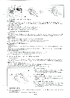
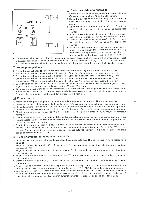
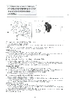
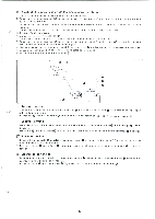
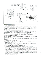
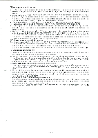
STANDARD ADJUSTMENTS STANDARDEINSTELLUNGEN REGLAGES STANDARD AJUSTES T Mark/Markierung/repere/Marca T rc; it L O Red dot Roter Punkt Trait rouge Punto rojo 2 mm Upper and Lower Shaft Timing Adjustment 1. Remove the needle and tilt the head back. 2. With the main lever shaft 0 depressed, turn the machine pulley in its normal rotating direction until it is hard to turn. 3. The T mark on the machine pulley scale must be in line with the red dot on the machine head. (The permissible deviation of the T mark from the center of the red dot is 2 mm.) * Belt installation 1. Remove the timing belt O. 2. Turn the machine pulley until the T mark is in line with the red dot. 3. With the main lever shaft 0 depressed, turn lower belt wheel 0 in the arrow direction until it is hard to turn. 4. Keep the machine pulley and lower belt wheel 0 still, and put the timing belt 0 on. ®. • Recheck the T mark on the machine pulley. • Never loosen the screws E Einstellung des Gleichlaufs der oberen und unteren Welle 1. Die Nadel abnehmen und das Maschinenoberteil aufklappen. 2. Bei gedriicktem Hebel 0 die Motorscheibe in normaler Drehrichtung drehen, bis ein Widerstand verspiirt wird. 3. Die T-Markierung auf der Riemenscheibe mull mit dem roten Punkt des Maschinenoberteils ausgerichtet sein. (Eine Abweichung von der T-Markierung zum roten Punkt bis zu 2 mm ist zulassig.) * Einbau des Riemens 1. Den Steuerriemen entfernen. 2. Die Riemenscheibe drehen, bis die T-Markierung mit dem roten Punkt ausgerichtet ist. 3. Bei gedrilicktem Hebel 0 die untere Riemenscheibe 0 in Pfeilrichtung drehen, bis ein Widerstand verspurt wird. 4. Die Motorscheibe und die untere Riemenscheibe 0 festhalten und den Riemen Q anbringen. X. Die Ausrichtung der T-Markierung auf dQr Motorscheibe noch einmal priden. • Die Schraube darf in keinem Fall gelost werden. ❑i Reglage de la synchronisation de l'arbre superieur et inferieur 1. Enlever l'aiguille et basculer la tete de la machine. 2. L'arbre du levier principal 0 etant enfonce, tourner la poulie de la machine manuellement dans son sens normal de rotation jusqu'a ce qu'elle devienne difficile a tourner. 3. Le repere T sur l'echelle de la poullie de la machine doit etre aligne avec le pointille rouge sur la tete de la machine. (Une deviation de 2 mm entre le repere T et l'axe du pointille rouge est admissible). Mise en place de la courroie 1. Enlever la courroie de synchronisation 0. 2. Tourner la poulie de la machine jusqu'a ce que le repere T soit aligns avec le pointille rouge. 3. L'arbre du levier principal &tent enfonce, tourner la poulie 0 de la courroie inferieuredans le sens indique par la fleche jusqu'a ce qu'elle devienne difficile a tourner. 4. Maintenir la poulie de la machine et la courroie inferieur immobiles et placer la courroie de synchronisation 0. • Reverifier l'emplacement du repere T sur la poulie de la machine. • Ne jamais desserrer les vis ®. 0 00
-
 1
1 -
2
-
3
-
4
-
5
-
6
-
7
-
8
-
9
-
10
-
 11
11 -
 12
12 -
 13
13 -
 14
14 -
 15
15 -
 16
16 -
 17
17 -
 18
18 -
 19
19 -
 20
20 -
 21
21 -
22
-
23
-
24
-
25
-
26
-
27
-
28
-
29
-
30
-
31
-
32
 |
 |
