Brother International LS2-B837 Instruction Manual - Page 18
down/thread
 |
View all Brother International LS2-B837 manuals
Add to My Manuals
Save this manual to your list of manuals |
Page 18 highlights
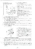
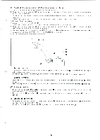
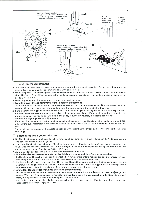
Low Tief Bas ' Bajo 1' Down needle stop position Anhalteposition bei tiefgestellter Nadel En arret des aiguilles en position basse En caso de detencion de aguja baja Low Tief Bas Bajo,t , High Hoch Haut Alto High Hoch Haut Alto About 25 mm 1- Up needle stop position Anhalteposition bei hochgestellter Nadel En arret des aiguilles en position haute En caso de detencien de aguja levantada Red dot Roter Punkt Point rouge Punto rojo _ A Mark Marke A A repere Marca A [10.5 - 11.5 mm 00 11 Synchronizer Adjustment * The needle position detector uses two elements to determine the needle position. Furthermore, it controls the needle down signal and thread trimmer signal with one element. * When the power is on and stopped in the needle down position, the distance from needle plate top to needle clamp should be 15 - 17 mm. When stopped in the needle up position, the distance from needle plate top to needle tip will be: 10.5 - 11.5 mm. * When adjusting any of the elements, be sure to turn off the power. • Needle down, thread trimming signal position adjustment 1. Turn the machine pulley in the normal rotational direction, and raise the needle bar 0 4 mm above the down position. (Align the needle bar reference line with the bottom edge of the needle bar bushing.) 2. If the magnet bottom and needle down/thread trimmer element 0 are not aligned, loosen set screw and move the needle down/thread trimmer element 0 to adjust so they are aligned. If the machine pulley is rotated in the normal direction, the needle bar will rise; if the pulley is turned in reverse, the needle bar will fall. O Needle up signal position adjustment 1. If the machine does not stop in the needle up position, loosen set screw 0 and move the needle up element 0 to adjust. If the pulley is rotated in the normal direction, the needle bar will fall; if rotated in reverse, the needle bar will rise. The needle can be stopped in the needle up position without cutting the thread by disconnecting the thread cutter switch 0. Einstellung des Synchronisators * Die Nadelposition wird durch zwei Teile bestimmt. Durch das eine Teil wird auflerdem auch die Nadelabbewegung und der Fadenabschneider ausgelost. * Wenn die Nadel bei eingeschalteter Maschine in der unteren Position steht, mug der Abstand zwischen der Stichplatte und der Nadelklammer 15 - 17 mm betragen. In der oberen Nadelposition betragt der Abstand wischen der Stichplatte und der Nadelspitze 10.5 - 11.5 mm. * Zum Einstellen der Teile mull die Stromzufuhr unterbrochen werden. O Einstellen des Auslosezeitpunkts der Nadelabbewegung und des Fadenabschneiders 1. Die Nadelstange 0 durch Drehen der Riemenscheibe 4 mm Ober die untere Position stellen. (Die Referenzlinie der Nadelstange mull mit der unteren Kante der Nadelstangenbuchse ausgerichtet sein.) 2. Die Schraube 0 Ibsen und das Teil 0 fur die Nadelabbewegung und den Fadenabschneider auf die Magnetunterseite Q ausrichten. Wenn die Riemenscheibe in normaler Drehrichtung gedreht wird, bewegt sich die Nadelstange nach oben, in umgekehrter Drehrichtung bewegt sie sich nach unten. Einstellen des Auslosezeitpunkts der Nadelaufbewegung 1. Falls die Maschine in der oberen Nadelposition nicht anhalt, mull die Schraube Q gelost und das Teil Ifl eingestellt werden. Wenn die Riemenscheibe in normaler Drehrichtung gedreht wird, bewegt sich die Nadelstange nach unten, in umgekehrter Drehrichtung bewegt sie sich nach oben. Die Nadel kann ohne den Faden durchzuschneiden in der oberen Position anhalten, wenn der Fadenabschneiderschalter 0 gelost wird.
-
 1
1 -
2
-
3
-
4
-
5
-
6
-
7
-
8
-
9
-
10
-
11
-
12
-
 13
13 -
 14
14 -
 15
15 -
 16
16 -
 17
17 -
 18
18 -
 19
19 -
 20
20 -
 21
21 -
 22
22 -
 23
23 -
24
-
25
-
26
-
27
-
28
-
29
-
30
-
31
-
32
 |
 |
