Cisco AIR-AP1252AG-A-K9 Hardware Installation Guide - Page 49
Connecting to an Ethernet Network with an Inline Power Source
 |
View all Cisco AIR-AP1252AG-A-K9 manuals
Add to My Manuals
Save this manual to your list of manuals |
Page 49 highlights
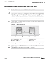
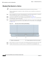
Chapter 2 Installing the Access Point Connecting the Ethernet and Power Cables Connecting to an Ethernet Network with an Inline Power Source Caution Be careful when handling the access point; the bottom plate might be hot. Note If your access point is connected to in-line power, do not connect the power module to the access point. Using two power sources on the access point might cause the access point to shut down to protect internal components and might cause the switch to shut down the port to which the access point is connected. If your access point shuts down, you must remove all power and reconnect only a single power source. Follow these steps to connect the access point to the Ethernet LAN when you have an inline power source: Step 1 Connect a Category 5E (or higher) Ethernet cable to the RJ-45 Ethernet connector labeled Ethernet on the access point (see Figure 2-15). Figure 2-15 Ethernet and Power Ports CAUTION EXTERNAL DC AND INLINE PoE POWER SOURCE REQUIREMENTS DETERMINED BY INSTALLED RADIO MODULES REFER TO PRODUCT DOCUMENTATION +56VDC ETHERNET CONSOLE MODE 230554 1 2 3 4 1 DC power connector (DC-IN) 2 Ethernet port (RJ-45) 3 Console port (RJ-45) 4 MODE button Step 2 Step 3 Step 4 Connect the other end of the Ethernet cable to the Ethernet connector on the 1250 series power injector labeled To AP. Connect a Category 5E (or higher) Ethernet cable from your your switch to the power injector connector labeled To Switch. Connect an AC power cord to the power injector and the AC wall socket. OL-8247-03 Cisco Aironet 1250 Series Access Point Hardware Installation Guide 2-21
-
 1
1 -
2
-
3
-
4
-
5
-
6
-
7
-
8
-
9
-
10
-
11
-
12
-
13
-
14
-
15
-
16
-
17
-
18
-
19
-
20
-
21
-
22
-
23
-
24
-
25
-
26
-
27
-
28
-
29
-
30
-
31
-
32
-
33
-
34
-
35
-
36
-
37
-
38
-
39
-
40
-
41
-
42
-
43
-
 44
44 -
 45
45 -
 46
46 -
 47
47 -
 48
48 -
 49
49 -
 50
50 -
 51
51 -
 52
52 -
 53
53 -
 54
54 -
55
-
56
-
57
-
58
-
59
-
60
-
61
-
62
-
63
-
64
-
65
-
66
-
67
-
68
-
69
-
70
-
71
-
72
-
73
-
74
-
75
-
76
-
77
-
78
-
79
-
80
-
81
-
82
-
83
-
84
-
85
-
86
-
87
-
88
-
89
-
90
-
91
-
92
-
93
-
94
-
95
-
96
-
97
-
98
-
99
-
100
-
101
-
102
-
103
-
104
-
105
-
106
-
107
-
108
-
109
-
110
-
111
-
112
-
113
-
114
-
115
-
116
-
117
-
118
-
119
-
120
-
121
-
122
-
123
-
124
-
125
-
126
-
127
-
128
-
129
-
130
-
131
-
132
-
133
-
134
-
135
-
136
-
137
-
138
-
139
-
140
-
141
-
142
 |
 |
