Cisco AIR-AP1252AG-A-K9 Hardware Installation Guide - Page 81
Running the Ping Test
 |
View all Cisco AIR-AP1252AG-A-K9 manuals
Add to My Manuals
Save this manual to your list of manuals |
Page 81 highlights
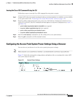
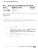
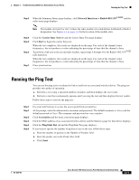
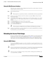
Chapter 3 Troubleshooting 1250 Series Autonomous Access Points Running the Ping Test Step 3 When the Summary Status page displays, click Network Interfaces > Radio0-802.11N2.4GHZ and the radio status page displays Note The module slot (slot 0 or slot 1) where the radio module is located defines the Radio0 or Radio1 designation. See Figure 1-1 on page 1-3 for the location of the module slots. Step 4 Step 5 Step 6 Step 7 Click the Carrier Busy Test tab and the Carrier Busy Test page displays Click Start to begin the carrier busy test. When the test completes, the results are displayed on the page. For each of the channel center frequencies, the test produces a value indicating the percentage of time that the channel is busy. To perform a link test on the second radio module, repeat steps 2 through 4 for the Radio1-802.11N5GHZ rado interfaces. When the test completes, the results are displayed on the page. For each of the channel center frequencies, the test produces a value indicating the percentage of time that the channel is busy. Close your browser. Running the Ping Test You can use the ping test to evaluate the link to and from an associated wireless device. The ping test provides two modes of operation: a. Performs a test using a specified number of packets and then displays the test results. b. Performs a test that continuously operates until you stop the test and then displays the test results. Follow these steps to activate the ping test: Step 1 Step 2 Step 3 Step 4 Step 5 Step 6 Use your web browser to access the access point browser interface. At the prompt, enter the administrator username and password. The default username is Cisco and the default password is Cisco. The username and password are case sensitive. Click Association and the main association page displays. Click the MAC address of an associated wireless device and the Statistics page for that device displays. Click the Ping/Link Test tab and the Ping/Link Test page displays. If you want to specify the number of packets to use in the test, follow these steps: a. Enter the number of packets in the Number of Packets field b. Enter the packet size in the Packet Size field. c. Click Start. OL-8247-03 Cisco Aironet 1250 Series Access Point Hardware Installation Guide 3-17
-
 1
1 -
2
-
3
-
4
-
5
-
6
-
7
-
8
-
9
-
10
-
11
-
12
-
13
-
14
-
15
-
16
-
17
-
18
-
19
-
20
-
21
-
22
-
23
-
24
-
25
-
26
-
27
-
28
-
29
-
30
-
31
-
32
-
33
-
34
-
35
-
36
-
37
-
38
-
39
-
40
-
41
-
42
-
43
-
44
-
45
-
46
-
47
-
48
-
49
-
50
-
51
-
52
-
53
-
54
-
55
-
56
-
57
-
58
-
59
-
60
-
61
-
62
-
63
-
64
-
65
-
66
-
67
-
68
-
69
-
70
-
71
-
72
-
73
-
74
-
75
-
 76
76 -
 77
77 -
 78
78 -
 79
79 -
 80
80 -
 81
81 -
 82
82 -
 83
83 -
 84
84 -
 85
85 -
 86
86 -
87
-
88
-
89
-
90
-
91
-
92
-
93
-
94
-
95
-
96
-
97
-
98
-
99
-
100
-
101
-
102
-
103
-
104
-
105
-
106
-
107
-
108
-
109
-
110
-
111
-
112
-
113
-
114
-
115
-
116
-
117
-
118
-
119
-
120
-
121
-
122
-
123
-
124
-
125
-
126
-
127
-
128
-
129
-
130
-
131
-
132
-
133
-
134
-
135
-
136
-
137
-
138
-
139
-
140
-
141
-
142
 |
 |
