Cisco AIR-AP1252AG-A-K9 Hardware Installation Guide - Page 87
Console Port and MODE Button Locations, Step 1
 |
View all Cisco AIR-AP1252AG-A-K9 manuals
Add to My Manuals
Save this manual to your list of manuals |
Page 87 highlights
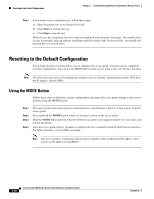
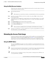
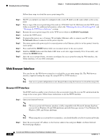
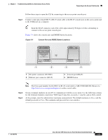
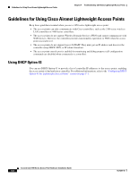
Chapter 3 Troubleshooting 1250 Series Autonomous Access Points Connecting to the Access Point Locally Follow these steps to open the CLI by connecting to the access point console port: Step 1 Connect a nine-pin, female DB-9 to RJ-45 serial cable to the RJ-45 console port on the access point and to the COM port on a computer. Tip Bend the RJ-45 connector end of the cable approximately 90 degrees before attempting to connect to the access point console port. Figure 3-4 shows the console port and MODE button locations. Figure 3-4 Console Port and MODE Button Locations 230554 CAUTION EXTERNAL DC AND INLINE PoE POWER SOURCE REQUIREMENTS DETERMINED BY INSTALLED RADIO MODULES REFER TO PRODUCT DOCUMENTATION +56VDC ETHERNET 1 2 1 DC power connector (56 VDC) 2 Ethernet port connector (RJ-45) CONSOLE MODE 3 4 3 Console port (RJ-45) 4 MODE button Note The Cisco part number for the DB-9 to RJ-45 serial cable is AIR-CONCAB1200. Browse to http://www.cisco.com/go/marketplace to order a serial cable. Step 2 Step 3 Set up a terminal emulator on your PC to communicate with the access point. Use the following settings for the terminal emulator connection: 9600 baud, 8 data bits, no parity, 1 stop bit, and no flow control. At the prompt, enter the administrator username and password. The default username is Cisco and the default password is Cisco. The username and password are case sensitive. OL-8247-03 Cisco Aironet 1250 Series Access Point Hardware Installation Guide 3-23
-
 1
1 -
2
-
3
-
4
-
5
-
6
-
7
-
8
-
9
-
10
-
11
-
12
-
13
-
14
-
15
-
16
-
17
-
18
-
19
-
20
-
21
-
22
-
23
-
24
-
25
-
26
-
27
-
28
-
29
-
30
-
31
-
32
-
33
-
34
-
35
-
36
-
37
-
38
-
39
-
40
-
41
-
42
-
43
-
44
-
45
-
46
-
47
-
48
-
49
-
50
-
51
-
52
-
53
-
54
-
55
-
56
-
57
-
58
-
59
-
60
-
61
-
62
-
63
-
64
-
65
-
66
-
67
-
68
-
69
-
70
-
71
-
72
-
73
-
74
-
75
-
76
-
77
-
78
-
79
-
80
-
81
-
 82
82 -
 83
83 -
 84
84 -
 85
85 -
 86
86 -
 87
87 -
 88
88 -
 89
89 -
 90
90 -
 91
91 -
 92
92 -
93
-
94
-
95
-
96
-
97
-
98
-
99
-
100
-
101
-
102
-
103
-
104
-
105
-
106
-
107
-
108
-
109
-
110
-
111
-
112
-
113
-
114
-
115
-
116
-
117
-
118
-
119
-
120
-
121
-
122
-
123
-
124
-
125
-
126
-
127
-
128
-
129
-
130
-
131
-
132
-
133
-
134
-
135
-
136
-
137
-
138
-
139
-
140
-
141
-
142
 |
 |
