Cisco AIR-AP1252AG-A-K9 Hardware Installation Guide - Page 51
Installing or Removing the Mounting Plate Latch
 |
View all Cisco AIR-AP1252AG-A-K9 manuals
Add to My Manuals
Save this manual to your list of manuals |
Page 51 highlights
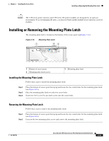
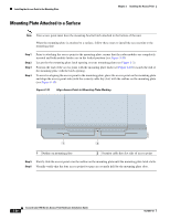
Chapter 2 Installing the Access Point Installing or Removing the Mounting Plate Latch Caution The 1250 series power injectors and 1250 series DC power modules are designed for an open-air environment. To avoid damaging the units, you must not bind together multiple power injectors or power modules. Installing or Removing the Mounting Plate Latch The mounting plate latch is located on the bottom of the access point (seeFigure 2-16). Figure 2-16 Mounting Plate Latch 1 23 OPEN LOCK 170360 48vDC 1 Bottom of access point 2 Mounting plate latch screws 3 Mounting plate latch Installing the Mounting Plate Latch Follow these steps to install the mounting plate latch: Step 1 Step 2 Step 3 Place the bottom of access point facing up and locate the two screw holes for the mounting plate latch (see Figure 2-16). Place the mounting plate latch over the two screw holes. Screw two 3/16 in (0.476 cm) 4x40 screws into the screw holes. Removing the Mounting Plate Latch Follow these steps to remove the mounting plate latch: Step 1 Step 2 Place the bottom of access point facing up and locate the two screw holes for the mounting plate latch (see Figure 2-16). Unscrew the two mounting plate screws and remove the mounting plate latch. OL-8247-03 Cisco Aironet 1250 Series Access Point Hardware Installation Guide 2-23
-
 1
1 -
2
-
3
-
4
-
5
-
6
-
7
-
8
-
9
-
10
-
11
-
12
-
13
-
14
-
15
-
16
-
17
-
18
-
19
-
20
-
21
-
22
-
23
-
24
-
25
-
26
-
27
-
28
-
29
-
30
-
31
-
32
-
33
-
34
-
35
-
36
-
37
-
38
-
39
-
40
-
41
-
42
-
43
-
44
-
45
-
 46
46 -
 47
47 -
 48
48 -
 49
49 -
 50
50 -
 51
51 -
 52
52 -
 53
53 -
 54
54 -
 55
55 -
 56
56 -
57
-
58
-
59
-
60
-
61
-
62
-
63
-
64
-
65
-
66
-
67
-
68
-
69
-
70
-
71
-
72
-
73
-
74
-
75
-
76
-
77
-
78
-
79
-
80
-
81
-
82
-
83
-
84
-
85
-
86
-
87
-
88
-
89
-
90
-
91
-
92
-
93
-
94
-
95
-
96
-
97
-
98
-
99
-
100
-
101
-
102
-
103
-
104
-
105
-
106
-
107
-
108
-
109
-
110
-
111
-
112
-
113
-
114
-
115
-
116
-
117
-
118
-
119
-
120
-
121
-
122
-
123
-
124
-
125
-
126
-
127
-
128
-
129
-
130
-
131
-
132
-
133
-
134
-
135
-
136
-
137
-
138
-
139
-
140
-
141
-
142
 |
 |
