Cisco AIR-AP1252AG-A-K9 Hardware Installation Guide - Page 54
Mounting Plate Attached to a Surface
 |
View all Cisco AIR-AP1252AG-A-K9 manuals
Add to My Manuals
Save this manual to your list of manuals |
Page 54 highlights
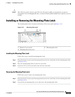
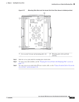
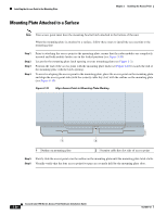
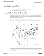
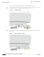
Installing the Access Point to the Mounting Plate Chapter 2 Installing the Access Point Mounting Plate Attached to a Surface Note Your access point must have the mounting bracket latch attached to the bottom of the unit. When the mounting plate is attached to a surface, follow these steps to install the access point to the mounting plate: Step 1 Step 2 Step 3 Step 4 Prior to attaching the access point to the mounting plate, ensure that the radio modules are completely inserted and both module latches are in the locked position (see Figure 2-24). Locate the the mounting plate latch opening on your mounting plate (see Figure 2-2). Position the end of the access point with the mounting plate latch (see Figure 2-16) towards the end of the mounting plate with the latch opening. To assist in aligning the access point to the mounting plate, place the access point on the mounting plate and align the access point side (with the security cable key slot) with the outline on the mounting plate (see Figure 2-18). Figure 2-18 Align Access Point to Mounting Plate Marking 230561 1 2 1 Outline on mounting plate 2 Security cable key slot side of access point Step 5 Slowly slide the access point over the outline on the mounting plate until the mounting plate latch clicks. Step 6 Visually verify that the four access point foot pins are securely held by the mounting plate slots. 2-26 Cisco Aironet 1250 Series Access Point Hardware Installation Guide OL-8247-03
-
 1
1 -
2
-
3
-
4
-
5
-
6
-
7
-
8
-
9
-
10
-
11
-
12
-
13
-
14
-
15
-
16
-
17
-
18
-
19
-
20
-
21
-
22
-
23
-
24
-
25
-
26
-
27
-
28
-
29
-
30
-
31
-
32
-
33
-
34
-
35
-
36
-
37
-
38
-
39
-
40
-
41
-
42
-
43
-
44
-
45
-
46
-
47
-
48
-
 49
49 -
 50
50 -
 51
51 -
 52
52 -
 53
53 -
 54
54 -
 55
55 -
 56
56 -
 57
57 -
 58
58 -
 59
59 -
60
-
61
-
62
-
63
-
64
-
65
-
66
-
67
-
68
-
69
-
70
-
71
-
72
-
73
-
74
-
75
-
76
-
77
-
78
-
79
-
80
-
81
-
82
-
83
-
84
-
85
-
86
-
87
-
88
-
89
-
90
-
91
-
92
-
93
-
94
-
95
-
96
-
97
-
98
-
99
-
100
-
101
-
102
-
103
-
104
-
105
-
106
-
107
-
108
-
109
-
110
-
111
-
112
-
113
-
114
-
115
-
116
-
117
-
118
-
119
-
120
-
121
-
122
-
123
-
124
-
125
-
126
-
127
-
128
-
129
-
130
-
131
-
132
-
133
-
134
-
135
-
136
-
137
-
138
-
139
-
140
-
141
-
142
 |
 |
