Cisco AIR-AP1252AG-A-K9 Hardware Installation Guide - Page 63
Module Latch Position During Module Installation, Step 3
 |
View all Cisco AIR-AP1252AG-A-K9 manuals
Add to My Manuals
Save this manual to your list of manuals |
Page 63 highlights
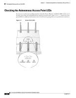
Chapter 2 Installing the Access Point Inserting a Radio Module Step 3 Slowly slide the radio module into the access point and ensure the module latch is properly positioned into the radio module notch (see Figure 2-27). Figure 2-27 Module Latch Position During Module Installation 1 230902 2 3 1 Radio module latch notch 2 Module latch 3 Latch open position Step 4 Use your thumb to push the module latch towards the lock position while squeezing with your fingers to push the radio module into the access point (see Figure 2-28). Continue pushing until the latch aligns with the Lock mark on the access point. OL-8247-03 Cisco Aironet 1250 Series Access Point Hardware Installation Guide 2-35
-
 1
1 -
2
-
3
-
4
-
5
-
6
-
7
-
8
-
9
-
10
-
11
-
12
-
13
-
14
-
15
-
16
-
17
-
18
-
19
-
20
-
21
-
22
-
23
-
24
-
25
-
26
-
27
-
28
-
29
-
30
-
31
-
32
-
33
-
34
-
35
-
36
-
37
-
38
-
39
-
40
-
41
-
42
-
43
-
44
-
45
-
46
-
47
-
48
-
49
-
50
-
51
-
52
-
53
-
54
-
55
-
56
-
57
-
 58
58 -
 59
59 -
 60
60 -
 61
61 -
 62
62 -
 63
63 -
 64
64 -
 65
65 -
 66
66 -
 67
67 -
 68
68 -
69
-
70
-
71
-
72
-
73
-
74
-
75
-
76
-
77
-
78
-
79
-
80
-
81
-
82
-
83
-
84
-
85
-
86
-
87
-
88
-
89
-
90
-
91
-
92
-
93
-
94
-
95
-
96
-
97
-
98
-
99
-
100
-
101
-
102
-
103
-
104
-
105
-
106
-
107
-
108
-
109
-
110
-
111
-
112
-
113
-
114
-
115
-
116
-
117
-
118
-
119
-
120
-
121
-
122
-
123
-
124
-
125
-
126
-
127
-
128
-
129
-
130
-
131
-
132
-
133
-
134
-
135
-
136
-
137
-
138
-
139
-
140
-
141
-
142
 |
 |

2-35
Cisco Aironet 1250 Series Access Point Hardware Installation Guide
OL-8247-03
Chapter 2
Installing the Access Point
Inserting a Radio Module
Step 3
Slowly slide the radio module into the access point and ensure the module latch is properly positioned
into the radio module notch (see
Figure 2-27
).
Figure 2-27
Module Latch Position During Module Installation
Step 4
Use your thumb to push the module latch towards the lock position while squeezing with your fingers to
push the radio module into the access point (see
Figure 2-28
). Continue pushing until the latch aligns
with the Lock mark on the access point.
1
Radio module latch notch
3
Latch open position
2
Module latch
230902
3
2
1