Cisco AIR-AP1252AG-A-K9 Hardware Installation Guide - Page 69
Checking Basic Settings, Default IP Address Behavior, Enabling the Radio Interfaces - default password
 |
View all Cisco AIR-AP1252AG-A-K9 manuals
Add to My Manuals
Save this manual to your list of manuals |
Page 69 highlights
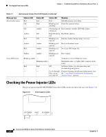
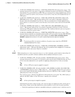
Chapter 3 Troubleshooting 1250 Series Autonomous Access Points Checking Basic Settings Table 3-2 lists the power injector LED indications. Table 3-2 Power Injector LED Indications LED AP Power Fault AC Power Color Green Red Green Description Indicates DC power is available to the access point. Indicates a short or overload condition. Check Ethernet cables and connections before contacting your support organization for assistance. Indicates AC power is available at the power injector. Checking Basic Settings Mismatched basic settings are the most common causes of lost connectivity with wireless clients. If the access point does not communicate with client devices, check the following areas. Default IP Address Behavior When you connect a 1250 series access point running Cisco IOS Release 12.4(10b)JA or later software with a default configuration to your LAN, the access point requests an IP address from your DHCP server and, if it does not receive an IP address, continues to send requests indefinitely. Enabling the Radio Interfaces In Cisco IOS Release 12.4(10b)JA or later, the access point radios are disabled by default, and there is no default SSID. You must create an SSID and enable the radios before the access point will allow wireless associations from other devices. These changes to the default configuration improve the security of newly installed access points. Refer to the Cisco IOS Software Configuration Guide for Cisco Aironet Access Points for instructions on configuring the SSID. To enable the radio interfaces, follow these instructions: Step 1 Step 2 Step 3 Use your web-browser to access your access point. At the prompt, enter the administrator username and password. The default username is Cisco and the default password is Cisco. The username and password are case sensitive. When the Summary Status page displays, click Network Interfaces > Radio0-802.11N2.4GHZ and the radio status page displays Note The module slot (slot 0 or slot 1) where the radio module is located defines the Radio0 or Radio1 designation. See Figure 1-1 on page 1-3 for the location of the module slots. Step 4 Step 5 Step 6 Step 7 Click Settings and the radio settings page displays. Click Enable in the Enable Radio field. Click Apply. Click Radio1-802.11N5GHZ and the radio status page displays. OL-8247-03 Cisco Aironet 1250 Series Access Point Hardware Installation Guide 3-5
-
 1
1 -
2
-
3
-
4
-
5
-
6
-
7
-
8
-
9
-
10
-
11
-
12
-
13
-
14
-
15
-
16
-
17
-
18
-
19
-
20
-
21
-
22
-
23
-
24
-
25
-
26
-
27
-
28
-
29
-
30
-
31
-
32
-
33
-
34
-
35
-
36
-
37
-
38
-
39
-
40
-
41
-
42
-
43
-
44
-
45
-
46
-
47
-
48
-
49
-
50
-
51
-
52
-
53
-
54
-
55
-
56
-
57
-
58
-
59
-
60
-
61
-
62
-
63
-
 64
64 -
 65
65 -
 66
66 -
 67
67 -
 68
68 -
 69
69 -
 70
70 -
 71
71 -
 72
72 -
 73
73 -
 74
74 -
75
-
76
-
77
-
78
-
79
-
80
-
81
-
82
-
83
-
84
-
85
-
86
-
87
-
88
-
89
-
90
-
91
-
92
-
93
-
94
-
95
-
96
-
97
-
98
-
99
-
100
-
101
-
102
-
103
-
104
-
105
-
106
-
107
-
108
-
109
-
110
-
111
-
112
-
113
-
114
-
115
-
116
-
117
-
118
-
119
-
120
-
121
-
122
-
123
-
124
-
125
-
126
-
127
-
128
-
129
-
130
-
131
-
132
-
133
-
134
-
135
-
136
-
137
-
138
-
139
-
140
-
141
-
142
 |
 |
