Compaq Pro 6300 Maintenance & Service Guide Elite 8300 Touch All-in-One Bu - Page 115
Front bezel
 |
View all Compaq Pro 6300 manuals
Add to My Manuals
Save this manual to your list of manuals |
Page 115 highlights
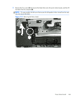
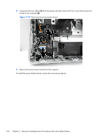
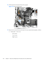
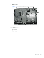
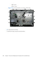
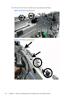
Front bezel The front bezel is located on the front of the computer and is secured to the main system bracket with eight Torx screws. Replacement bezels include the webcam shutter and capacitive sensor board. On models that do not include a webcam, you must remove the shutter and install the webcam insert (Webcam assembly kit) into the slot in which the webcam would otherwise be installed. To remove the front bezel: 1. Prepare the computer for disassembly (see Preparing to disassemble the computer on page 40). 2. Remove the access panel (see Access panel on page 45). 3. Remove the stand (see Stand on page 48). 4. Remove the lower panel (see Lower panel on page 50). 5. Remove the optical drive (see Replacing the optical disc drive on page 57). 6. Remove the metal plate (see Metal plate on page 51). 7. Remove the power supply (see Power supply on page 90). 8. Remove the side panels (see Side panels on page 88). 9. Remove the speakers (see Speakers on page 86). 10. Remove the power button board (see Power button board on page 102). Front bezel 105
-
 1
1 -
2
-
3
-
4
-
5
-
6
-
7
-
8
-
9
-
10
-
11
-
12
-
13
-
14
-
15
-
16
-
17
-
18
-
19
-
20
-
21
-
22
-
23
-
24
-
25
-
26
-
27
-
28
-
29
-
30
-
31
-
32
-
33
-
34
-
35
-
36
-
37
-
38
-
39
-
40
-
41
-
42
-
43
-
44
-
45
-
46
-
47
-
48
-
49
-
50
-
51
-
52
-
53
-
54
-
55
-
56
-
57
-
58
-
59
-
60
-
61
-
62
-
63
-
64
-
65
-
66
-
67
-
68
-
69
-
70
-
71
-
72
-
73
-
74
-
75
-
76
-
77
-
78
-
79
-
80
-
81
-
82
-
83
-
84
-
85
-
86
-
87
-
88
-
89
-
90
-
91
-
92
-
93
-
94
-
95
-
96
-
97
-
98
-
99
-
100
-
101
-
102
-
103
-
104
-
105
-
106
-
107
-
108
-
109
-
 110
110 -
 111
111 -
 112
112 -
 113
113 -
 114
114 -
 115
115 -
 116
116 -
 117
117 -
 118
118 -
 119
119 -
 120
120 -
121
-
122
-
123
-
124
-
125
-
126
-
127
-
128
-
129
-
130
-
131
-
132
-
133
-
134
-
135
-
136
-
137
-
138
-
139
-
140
-
141
-
142
-
143
-
144
-
145
-
146
-
147
-
148
-
149
-
150
-
151
-
152
-
153
-
154
-
155
-
156
-
157
-
158
-
159
-
160
-
161
-
162
-
163
-
164
-
165
-
166
-
167
-
168
-
169
-
170
-
171
-
172
-
173
-
174
-
175
-
176
-
177
-
178
-
179
-
180
-
181
-
182
-
183
-
184
-
185
-
186
-
187
-
188
-
189
-
190
-
191
-
192
-
193
-
194
-
195
-
196
-
197
-
198
-
199
-
200
-
201
-
202
-
203
-
204
-
205
-
206
-
207
-
208
 |
 |
