D-Link DES-1210-52 Product Manual - Page 10
DES-1210-28P, Port Link/Act/Speed LED 25F, 26F, 25T, 26T - 28p manual
 |
UPC - 790069327827
View all D-Link DES-1210-52 manuals
Add to My Manuals
Save this manual to your list of manuals |
Page 10 highlights
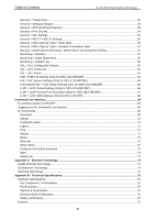
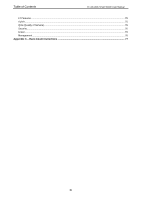
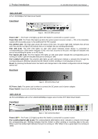
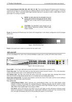
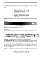
1 Product Introduction D-Link Web Smart Switch User Manual Port Link/Act/Speed LED (25F, 26F, 25T, 26T, 27, 28): The Link/Act/Speed LED flashes which indicates a network link through the corresponding port. Blinking indicates that the Switch is either sending or receiving data to the port. When a port has amber light indicates that port is running on 10M or 100M. When it has a green light it is running on 1000M. NOTE: On DES-1210-28, the MiniGBIC ports are shared with normal RJ-45 ports 25 and 26. When MiniGBIC port is used, the RJ-45 port cannot be used. CAUTION: The MiniGBIC ports should use UL listed Optical Transceiver product, Rated Laser Class I. 3.3Vdc. Reset: By pressing the Reset button the Switch will change back to the default configuration and all changes will be lost. Rear Panel Figure 4 - DES-1210-28 Rear Panel Power: The power port is where to connect the AC power cord. DES-1210-28P 24-Port 10/100Mpbs PoE with 4-Port 10/100/1000Mbps Copper and 2 Combo SFP Web Smart Switch Front Panel Figure 5 - DES-1210-28P Front Panel Power LED : The Power LED lights up when the Switch is connected to a power source. Power Max LED: The Power Max lights up when the system power resource remain ≦7W, in the meantime, system will not provide power to the additional PoE PD inserted. Fan OK/Fail LED: The FAN LED shows the status of the fans, the green light (OK) indicates that all fans work fine and the red light (Fail) indicate that on or multiple fans are working abnormally. Mode Select Button/LED: The Mode Select Button controls the mode of Port LED, and the current setting is indicated by the Mode LED under the button. Port LED (1-24): Link/Act/Speed Mode: When selecting the Link/Act/Speed Mode, the Port LED flashes which indicate a network link through the corresponding port. Blinking indicates that the Switch is either sending or receiving data to the port. When a port has amber light indicates that port is running on 10M. When it has a green light it is running on 100M. PoE Mode: When selecting the PoE Mode, the port LED lights up with solid green indicates power device is connected to corresponding port. Solid amber indicates a PoE error has occurred at this port. And light off indicates this port is not providing the power or no PD found. 4
-
 1
1 -
2
-
3
-
4
-
 5
5 -
 6
6 -
 7
7 -
 8
8 -
 9
9 -
 10
10 -
 11
11 -
 12
12 -
 13
13 -
 14
14 -
 15
15 -
16
-
17
-
18
-
19
-
20
-
21
-
22
-
23
-
24
-
25
-
26
-
27
-
28
-
29
-
30
-
31
-
32
-
33
-
34
-
35
-
36
-
37
-
38
-
39
-
40
-
41
-
42
-
43
-
44
-
45
-
46
-
47
-
48
-
49
-
50
-
51
-
52
-
53
-
54
-
55
-
56
-
57
-
58
-
59
-
60
-
61
-
62
-
63
-
64
-
65
-
66
-
67
-
68
-
69
-
70
-
71
-
72
-
73
-
74
-
75
-
76
-
77
-
78
-
79
-
80
-
81
-
82
-
83
-
84
-
85
 |
 |