D-Link DES-1210-52 Product Manual - Page 41
System > System Log Settings, System > Password Access Control - 28 default password
 |
UPC - 790069327827
View all D-Link DES-1210-52 manuals
Add to My Manuals
Save this manual to your list of manuals |
Page 41 highlights
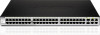
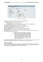
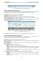
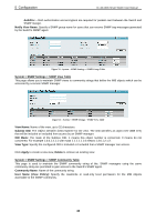
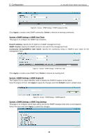
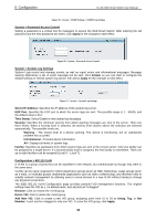
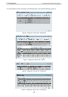
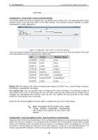
5 Configuration D-Link Web Smart Switch User Manual Figure 59 - System > SNMP Settings > SNMP Trap Setting System > Password Access Control Setting a password is a critical tool for managers to secure the Web-Smart Switch. After entering the old password and the new password two times, click Apply for the changes to take effect. Figure 60 - System > Password Access Control System > System Log Settings System Logs record and manage events, as well as report errors and informational messages. Message severity determines a set of event message will be sent. Click Enable so you can start to configure the related settings of remote system log server, then press Apply for the changes to take effect. Figure 61 - System > System Log Settings Server IP Address: Specifies the IP address of the system log server. UDP Port: Specifies the UDP port to which the server logs are sent. The possible range is 1 - 65535, and the default value is 514. Time Stamp: Select Enable to time stamp log messages. Severity: Specifies the minimum severity from which warning messages are sent to the server. There are three levels. When a severity level is selected, all severity level choices above the selection are selected automatically. The possible levels are: Warning - The lowest level of a device warning. The device is functioning, but an operational problem has occurred. Informational - Provides device information. All - Displays all levels of system logs. Facility: Specifies an application from which system logs are sent to the remote server. Only one facility can be assigned to a single server. If a second facility level is assigned, the first facility is overwritten. There are up to eight facilities can be assigned (Local 0 ~ Local 7), Configuration > 802.1Q VLAN A VLAN is a group of ports that can be anywhere in the network, but communicate as though they were in the same area. VLANs can be easily organized to reflect department groups (such as R&D, Marketing), usage groups (such as e-mail), or multicast groups (multimedia applications such as video conferencing), and therefore help to simplify network management by allowing users to move devices to a new VLAN without having to change any physical connections. The IEEE 802.1Q VLAN Configuration page provides powerful VID management functions. The original settings have the VID as 1, no default name, and all ports as "Untagged" Rename: Click to rename the VLAN group. Delete VID: Click to delete the VLAN group. Add New VID: Click to create a new VID group, assigning ports from 01 to 28 as Untag, Tag, or Not Member. A port can be untagged in only one VID. To save the VID group, click Apply. 35
-
 1
1 -
2
-
3
-
4
-
5
-
6
-
7
-
8
-
9
-
10
-
11
-
12
-
13
-
14
-
15
-
16
-
17
-
18
-
19
-
20
-
21
-
22
-
23
-
24
-
25
-
26
-
27
-
28
-
29
-
30
-
31
-
32
-
33
-
34
-
35
-
 36
36 -
 37
37 -
 38
38 -
 39
39 -
 40
40 -
 41
41 -
 42
42 -
 43
43 -
 44
44 -
 45
45 -
 46
46 -
47
-
48
-
49
-
50
-
51
-
52
-
53
-
54
-
55
-
56
-
57
-
58
-
59
-
60
-
61
-
62
-
63
-
64
-
65
-
66
-
67
-
68
-
69
-
70
-
71
-
72
-
73
-
74
-
75
-
76
-
77
-
78
-
79
-
80
-
81
-
82
-
83
-
84
-
85
 |
 |