D-Link DFL-200 Product Manual
D-Link DFL-200 - Security Appliance Manual
 |
UPC - 790069268823
View all D-Link DFL-200 manuals
Add to My Manuals
Save this manual to your list of manuals |
D-Link DFL-200 manual content summary:
- D-Link DFL-200 | Product Manual - Page 1
D-Link DFL-200 TM Network Security Firewall Manual Building Networks for People (04/18/2005) - D-Link DFL-200 | Product Manual - Page 2
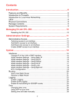
to Firewalls 6 Introduction to Local Area Networking 7 LEDs ...8 Physical Connections 8 Package Contents 9 System Requirements 9 Managing D-Link DFL-200 10 Resetting the DFL-200 10 Administration Settings 11 Administrative Access 11 Add ping access to an interface 12 Add Admin access - D-Link DFL-200 | Product Manual - Page 3
Delete policy 29 Configure Intrusion Detection 29 Configure Intrusion Prevention 29 Port mapping / Virtual Servers 30 Add a new mapping 30 Delete mapping 31 Administrative users 32 Change Administrative User Password 32 Users 33 The DFL-200 RADIUS Support 33 Enable User Authentication via - D-Link DFL-200 | Product Manual - Page 4
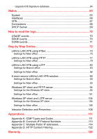
DNS Relayer 58 Tools 59 Ping ...59 Ping Example 59 Dynamic DNS 60 Add Dynamic DNS Settings 60 Backup 61 Exporting the DFL-200's Configuration 61 Restoring the DFL-200's Configuration 61 Restart/Reset 62 Restoring system settings to factory defaults 63 Upgrade 64 Upgrade Firmware 64 4 - D-Link DFL-200 | Product Manual - Page 5
events 71 Step by Step Guides 72 LAN-to-LAN VPN using IPSec 73 Settings for Main office 75 LAN-to-LAN VPN using PPTP 77 Settings for Main office 79 LAN-to-LAN VPN using L2TP 83 Settings for Branch office 83 Settings for Main office 86 A more secure LAN-to-LAN VPN solution 90 Settings for - D-Link DFL-200 | Product Manual - Page 6
External/WAN, and (1) DMZ port. In addition the DFL-200 also provides a user-friendly Web UI that allows users to set system parameters or monitor network activities using a Web browser supporting Java. Features and Benefits z Firewall Security z VPN Server/Client Supported Supports IPSec LAN-to-LAN - D-Link DFL-200 | Product Manual - Page 7
a switch can determine the destination port for a specific piece of data. A switch minimizes network traffic overhead and speeds up the communication over a network. Networks take some time in order to plan and implement correctly. There are many ways to configure your network. You may want to take - D-Link DFL-200 | Product Manual - Page 8
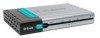
service an additional physically segmented Private or Transparent Network to be occupied by WAN accessible servers (FTP, HTTP, DNS). WAN Port: Use this port to connect to an external network, such as a WAN or a modem provided by an ISP. Reset: Use this switch to reset the DFL-200 to factory default - D-Link DFL-200 | Product Manual - Page 9
Link DFL-200 Firewall • Manual and CD • Quick Installation Guide • 5V/3A AC Power adapter • Straight-through CAT-5 cable • RS-232 Null Modem Cable Note: Using a power supply with a different voltage rating than the one included with the DFL-200 adapter configured to communicate using TCP/IP. • - D-Link DFL-200 | Product Manual - Page 10
has been reached, otherwise the DFL-200 will revert to the previous configuration. The timeout can be set on the Activate Configuration Changes page, by choosing the time from the dropdown menu. Resetting the DFL-200 To reset the DFL-200 to factory default settings simply press down and hold - D-Link DFL-200 | Product Manual - Page 11
login). Ping - If enabled, it specifies who can ping the IP interface of the DFL-200. Enabling Default allows anyone to ping the interface IP. Admin - If enabled, it allows all users with admin access to connect to the DFL-200 and change configuration; this can be HTTPS or HTTP and HTTPS. Read-Only - D-Link DFL-200 | Product Manual - Page 12
interface, for example 192.168.1.0/24 for a whole class C network or 172.16.0.1 - 172.16.0.10 for a range of IP addresses. Step 4. Specify protocol to be used to access the DFL-200 via the dropdown menu. Select HTTP and HTTPS (Secure HTTP) or HTTPS only. Click the Apply button below to apply - D-Link DFL-200 | Product Manual - Page 13
you only have read-only access enabled on an interface, all users will only have read-only access, even if they are network or 172.16.0.1 - 172.16.0.10 for a range of IP addresses. Step 4. Specify protocol to be used to access the DFL-200 via the dropdown menu. Select HTTP and HTTPS (Secure - D-Link DFL-200 | Product Manual - Page 14
with the new LAN IP. If the computer through which the DFL-200 is being configured is a DHCP client, you will need to manually release and renew the IP address after applying changes and restarting. Failure to follow these directions will result in the firewall configuration reverting back to the - D-Link DFL-200 | Product Manual - Page 15
is the address that may be used to ping the firewall, remotely control it, and be used as the source address for dynamically translated connections. • Subnet Mask - Size of the external network. • Gateway IP - Specifies the IP address of the default gateway used to access the Internet. • Primary and - D-Link DFL-200 | Product Manual - Page 16
the following procedure to configure the DFL-200 external interface to use PPPoE (Point-to-Point Protocol over Ethernet). This configuration is required if your ISP uses PPPoE to assign the IP address of the external interface. You will have to fill in the username and password provided to you by - D-Link DFL-200 | Product Manual - Page 17
networks. You need to enter your account details, and possibly also IP configuration parameters of the actual physical interface that the PPTP tunnel your ISP. • Password - The password supplied to you by your ISP. • PPTP Server IP - The IP of the PPTP server that the DFL-200 will connect to. Before - D-Link DFL-200 | Product Manual - Page 18
modem networks. You need to enter your account details, and possibly also IP configuration parameters of the actual physical interface that the L2TP tunnel runs over. Your ISP should supply this information. • Username - The login or username supplied to you by your ISP. • Password - The password - D-Link DFL-200 | Product Manual - Page 19
Password - The password supplied to you by your ISP. MTU Configuration To improve the performance of your Internet connection, you can adjust the maximum transmission unit (MTU) of the packets that the DFL-200 networks have an MTU of 1500. Note: If you connect to your ISP using DHCP to obtain an IP - D-Link DFL-200 | Product Manual - Page 20
this: The Routes configuration section describes the firewall's routing table. The DFL-200 uses a slightly different method of describing routes compared to most other systems. However, we believe that this method of describing routes is easier to understand, making it less likely for users to cause - D-Link DFL-200 | Product Manual - Page 21
the route should be sent through from the dropdown menu. Step 4. Specify the Network and Subnet mask. Step 5. If this network is behind a remote gateway, enable the checkbox Network is behind remote gateway and specify the IP of that gateway. Click the Apply button below to apply the settings or - D-Link DFL-200 | Product Manual - Page 22
then click Logging below it. Logging, the ability to audit decisions made by the firewall, is a vital part in all network security products. The D-Link DFL-200 provides several options for logging activity. The DLink DFL-200 logs activity by sending the log data to one or two log receivers in the - D-Link DFL-200 | Product Manual - Page 23
Link DFL-200 specifies a number of events that can be logged. Some of these events, such as startup and shutdown, are mandatory and will always generate log entries. Other events, for instance when allowed connections are opened and closed, are configurable the default facility. the firewall, follow - D-Link DFL-200 | Product Manual - Page 24
Time Click on System in the menu bar, and then click Time below it. This will give you the option to either set the system time by synchronizing with an Internet Network Time Server (NTP) or by entering the system time manually. 24 - D-Link DFL-200 | Product Manual - Page 25
synchronization by checking the Enable NTP box. Step 2. Enter the Server IP Address or Server name with which you want to synchronize. Click the or click Cancel to discard changes. Setting time and date manually Follow these steps to manually set the system time. Step 1. Check the Set the system - D-Link DFL-200 | Product Manual - Page 26
. Policy modes The first step in configuring security policies is to configure the mode for the firewall. The firewall can run in NAT or No NAT (Route) mode. Select NAT mode to use DFL-200 network address translation to protect private networks from public networks. In NAT mode, you can connect - D-Link DFL-200 | Product Manual - Page 27
an attack, the IDS will protect the networks behind the DFL-200 by dropping the traffic. To notify responsible parties of the malicious attack, the IDS will send e-mails to the system administrators if e-mail alerting is enabled and configured. D-Link updates the attack database periodically. There - D-Link DFL-200 | Product Manual - Page 28
traffic to traverse the firewall. Choose Deny to drop all traffic matching the criteria of the specified service. Source Nets: - Specifies the sender span of IP addresses to be compared to the received packet. Leave this blank to match everything. Source Users/Groups: Specifies if an authenticated - D-Link DFL-200 | Product Manual - Page 29
IDS on a policy. Step 1. Choose the policy you would like to have IDS on. Step 2. Click on the Edit link corresponding to the rule you want to configure. Step 3. Enable the Intrusion Detection / Prevention checkbox. Step 4. Choose Inspection Only from the mode drop down list. Step 5. Enable - D-Link DFL-200 | Product Manual - Page 30
Port mapping / Virtual Servers The Port mapping / Virtual Servers configuration section is where you can configure virtual servers (such as a LAN Web server) to allow WAN access to specified LAN or DMZ servers. It is also possible to use Intrusion Detection / Prevention on Port mapped services. - D-Link DFL-200 | Product Manual - Page 31
Follow these steps to delete a mapping. Step 1. Choose the mapping list (WAN, LAN, or DMZ) you would like do delete the mapping from. Step 2. Click on the Edit link corresponding to the rule you want to delete. Step 3. Enable the Delete mapping checkbox. Click the Apply button below to apply the - D-Link DFL-200 | Product Manual - Page 32
Click on Firewall in the menu bar, and then click Users below it. This will display all the users. The first section links to the administrative user. The password for the admin account may be changed at any time, however the username admin cannot be altered. Change Administrative User Password To - D-Link DFL-200 | Product Manual - Page 33
to other authentication services. The DFL-200 RADIUS Support The DFL-200 can use RADIUS to verify users against, for example, Active Directory or Unix password-file. It is possible to configure up to two servers, if the first one is down it will try the second IP instead. The DFL-200 can use CHAP - D-Link DFL-200 | Product Manual - Page 34
the firewall. Step 4. Choose new ports for the web-based management GUI to listen on since enabling user authentication requires the default ports for user login purposes (80 and 443). Click the Apply button below to apply the settings or click Cancel to discard changes. Enable RADIUS Support Follow - D-Link DFL-200 | Product Manual - Page 35
add corresponding to the type of user you would like to add, Admin or Read-only. Step 2. Fill in User name; make sure you are not trying to add one that already exists. Step 3. Specify which groups the user should be a member of. Step 3. Specify the password for the new user. Click the Apply button - D-Link DFL-200 | Product Manual - Page 36
. Follow these steps to delete a user. Step 1. Click on the user you would like to delete. Step 2. Enable the Delete user checkbox. Click the Apply button below to apply the settings or click Cancel to discard changes. Note: Deleting a user is irreversible; once the user is deleted, it cannot be - D-Link DFL-200 | Product Manual - Page 37
not likely be permitted to pass through the firewall. The DFL-200 can be configured to have a start time and stop time, as well as 2 different time periods in a day. For example, an organization may only want the firewall to allow the internal network users to access the Internet during work hours - D-Link DFL-200 | Product Manual - Page 38
Add new one-time schedule Follow these steps to create and add a new one-time schedule. Step 1. Go to Firewall and Schedules and choose Add new. Step 2. Choose the starting and ending date and hour when the schedule should be active. Step 3. Use the checkboxes - D-Link DFL-200 | Product Manual - Page 39
a definition of a specific IP protocol with corresponding parameters. The service http, for instance, is defined as using the TCP protocol with destination port 80. Services are simplistic, in that they cannot carry out any action in the firewall on their own. Thus, a service definition does not - D-Link DFL-200 | Product Manual - Page 40
to the TCP and UDP port range described previously. The range 1-4, 7 will match the protocols ICMP, IGMP, GGP, IP-in-IP, and CBT. Follow these steps to add a TCP, UDP, or TCP/UDP service. Step 1. Go to Firewall and Service and choose new. Step 2. Enter a Name for the service in the name field. This - D-Link DFL-200 | Product Manual - Page 41
will thus manage network traffic that matches the policy using this service. Currently, the DFL-200 supports two Application Layer Gateways, one is used to manage the FTP protocol and the other one is a HTTP Content Filtering ALG. For detailed information about how to configure the HTTP Application - D-Link DFL-200 | Product Manual - Page 42
defined by the IETF, Internet Engineering Task Force, to provide IP security at the network layer. An IPSec based VPN, such as that of the DFL-200, is made up of two basic parts: • Internet Key Exchange security protocol (IKE) • IPSec protocol (ESP) The first part, IKE, is the initial negotiation - D-Link DFL-200 | Product Manual - Page 43
Introduction to L2TP L2TP, Layer 2 Tunneling Protocol, a combination of Microsoft's PPTP and Cisco's L2F (Layer 2 Forwarding), is used to provide IP security at the network layer. An L2TP based VPN is made up by these parts: • Point-to-Point Protocol (PPP) • Authentication Protocols (PAP, CHAP, MS- - D-Link DFL-200 | Product Manual - Page 44
user name and password are sent over the tunnel plaintext. PAP is therefore not considered a secure challenge issued by the DFL-200. CHAP is superior to PAP in that the password is never sent over the link. Instead the password is used to create supports 40-bit, 56-bit and 128-bit RC4 session keys. 44 - D-Link DFL-200 | Product Manual - Page 45
L2TP/PPTP Client Configuration Name - Specifies a friendly name for the PPTP/L2TP Client tunnel. Username - Specify the username for this PPTP/L2TP Client tunnel. Password/Confirm Password - The password to use for this PPTP/L2TP Client tunnel. Interface IP - Specifies if the L2TP/PPTP Client tunnel - D-Link DFL-200 | Product Manual - Page 46
for L2TP/PPTP Server Configuration Name - Specifies a name for this PPTP/L2TP Server. Outer IP - Specifies the IP that the PPTP/L2TP server should listen on, leave it Blank for the WAN IP. Inner IP - Specifies the internal IP of the VPN tunnel. Leave this field Blank for the LAN IP. IP Pool - D-Link DFL-200 | Product Manual - Page 47
be configured as IPSec VPN gateways to create a VPN tunnel that connects the branch office network to the main office network. DFL-200 Firewall The example shows an IPSec VPN between two internal networks. One may also create VPN tunnels between an internal network behind one VPN gateway and a DMZ - D-Link DFL-200 | Product Manual - Page 48
. DFL-200 Firewall The example shows a VPN between a roaming VPN client and the internal network, but you can also create a VPN tunnel that uses the DMZ network. The networks at the ends of the VPN tunnel are selected when you configure the VPN policy. Creating a Roaming Users IPSec Tunnel Follow - D-Link DFL-200 | Product Manual - Page 49
. Adding an L2TP/PPTP VPN Server Follow these steps to add an L2TP or PPTP VPN Server configuration that listens on the WAN IP. Step 1. Go to Firewall and VPN and choose Add new PPTP server or Add new L2TP server in the L2TP/PPTP Server section. Step 2. Enter a Name for this tunnel in the name - D-Link DFL-200 | Product Manual - Page 50
On if supported - Always tries to use NAT-T when setting up the tunnel. Keepalives No keepalives - Keep-alive is disabled. Automatic keepalives - The firewall will send ICMP pings to IP Addresses automatically discovered from the VPN Tunnel settings. Manually configured IP addresses - Configure the - D-Link DFL-200 | Product Manual - Page 51
algorithms. Life Times - Specifies in KB or seconds when the security associations for the VPN tunnel need to be re-negotiated. IPSec Proposal List Cipher - Specifies the encryption algorithm used in this IPSec proposal. Supported algorithms are AES, 3DES, DES, Blowfish, Twofish, and CAST128. HMAC - D-Link DFL-200 | Product Manual - Page 52
. It links an identity to a public key in a trustworthy manner. Certificates can be used to authenticate individual users or other entities. These types of certificates are commonly called end-entity certificates. Before a VPN tunnel with certificate based authentication can be set up, the firewall - D-Link DFL-200 | Product Manual - Page 53
Identity list can be selected in the Identity List field on the VPN page. If an Identity List is configured, the firewall will match the identity of the connecting remote peer against the Identity List, and only allow it to open the VPN tunnel if it matches the contents of the list. If no Identity - D-Link DFL-200 | Product Manual - Page 54
between the requested URL and the URL Blacklist the DFL-200 will block the Web page. You can configure the URL Blacklist to block all or just some ActiveX, Java, Flash, or cookies). Note: For HTTP URL filtering to work, all HTTP traffic needs to go through a policy using a service with the HTTP - D-Link DFL-200 | Product Manual - Page 55
pre-defined "HTTP-outbound TCP: All -> 80 ALG: "http-cf", max 100" service is provided to simplify the configuration of HTTP Content Filtering. Refer to Appendix D for more detailed information on configuration of HTTP Content Filtering. Active content handling Active content handling can be enabled - D-Link DFL-200 | Product Manual - Page 56
and manages IP addresses from specified address pools within the firewall to the DHCP clients. Note: Leases are remembered over a re-configure or reboot of the firewall. The DFL-200 also includes a DHCP Relay function. A DHCP Relay allows the DFL-200 to receive DHCP requests and forward those - D-Link DFL-200 | Product Manual - Page 57
IP for the range of IP addresses that the DFL200 can assign. Step 4. Fill in the DNS servers the DHCP server will assign to the clients; at least one should be provided. If the DNS Relay function is configured is coming from, i.e. a server on the DMZ. Click the Apply button below to apply the - D-Link DFL-200 | Product Manual - Page 58
that can be configured to relay DNS queries from the internal LAN to the DNS servers used by the firewall itself. Enable DNS Relayer Follow these steps to enable the DNS Relayer. Step 1. Enable by checking the Enable DNS Relayer box. Step 2. Enter the IP numbers that the DFL-200 should listen for - D-Link DFL-200 | Product Manual - Page 59
second. This method is the best suited for diagnosing connectivity problems. • IP Address - Target IP to send the ICMP Echo Requests to. • Number packets is five. After clicking on Apply the firewall will start to send the ICMP Echo Requests to the specified IP. After a few seconds the result will - D-Link DFL-200 | Product Manual - Page 60
IP address provided by ISP. Click DynDNS in the Tools menu to enter Dynamic DNS configuration. The firewall provides a list of a few predefined DynDNS service providers. Users what Dynamic DNS service you would like to use, and fill in the required information, username and password in all cases and - D-Link DFL-200 | Product Manual - Page 61
file stores system settings, IP addresses of the firewall's network interfaces, address table, service table, IPSec settings, port mapping, and policies. When the configuration process is completed, a system administrator can download the configuration file onto a local disc - D-Link DFL-200 | Product Manual - Page 62
Restart/Reset Restarting the DFL-200 Follow these steps restart the DFL-200. Step 1. Choose if you want to do a quick or full restart. Step 2. Click Restart Unit and the unit will restart. 62 - D-Link DFL-200 | Product Manual - Page 63
change the DFL-200 firmware version to a lower version if it has been upgraded. Make sure you have the current firmware file available for upload to the device in the case where the firmware version is defaulted to an older version. The factory reset procedure erases all configuration changes that - D-Link DFL-200 | Product Manual - Page 64
are all stored on a flash memory card. The flash memory card is rewritable and re-readable. Upgrade Firmware To upgrade the firmware of the DFL-200, obtain the latest version from support.dlink.com (US). Make sure the firmware file is stored on the PC connected to the firewall. Connect to the web - D-Link DFL-200 | Product Manual - Page 65
about the DFL-200. Uptime - The time the firewall has been running, since the last reboot or start. Time - The current time and date. Configuration - Shows when the last administrative configuration change was activated as well as the originating IP. Firmware version - The firmware version - D-Link DFL-200 | Product Manual - Page 66
information about the interfaces on the DFL-200. By default, information about the LAN interface will be displayed. To see another one, click on that interface (WAN or DMZ). Interface - Name of the interface shown, LAN, WAN, or DMZ. Link status - Displays what link the current interface has. The - D-Link DFL-200 | Product Manual - Page 67
then click Interfaces below it. A window will appear providing information about the VPN connections on the DFL-200. By default information about the first VPN tunnel will be displayed. To see another one, click on that VPN tunnels name. The two graphs display the send and receive rate through the - D-Link DFL-200 | Product Manual - Page 68
two timeout values, one in each direction. These are updated when the firewall receives packets from each end of the connection. The value shown in - The connection uses an IP protocol other than TCP, UDP, or ICMP. The Source and Destination columns show which IP and port on the source interface the - D-Link DFL-200 | Product Manual - Page 69
configured DHCP Servers. By default, information about the LAN interface will be displayed. To see another one, click on that interface. Interface - Name of the interface the DHCP Server is running on. IP Span - Displays the configured range of IP corresponding to that IP. Inactive leases are - D-Link DFL-200 | Product Manual - Page 70
preface each log entry with a timestamp and the IP address of the machine that sent the log data: =dmz ip3=192.168.1.1 tp3=0.99 The value after "conns" is the number of open connections through the firewall when firewall, connecting to 192.168.10.1 on port 135 is dropped. The protocol used is TCP. 70 - D-Link DFL-200 | Product Manual - Page 71
protocol, receiving interface, source IP address, source port, destination interface, destination IP address, and destination port. Open Example: Oct 20 10 on the LAN interface is connecting to 64.7.210.132 on port 80 on the WAN side of the firewall (internet). Another event is generated when the - D-Link DFL-200 | Product Manual - Page 72
recommended for real life use. Strong passwords and keys should be chosen making use of symbols, letters, and numbers to decrease the likelihood of a brute force dictionary attack success. In these guides for example Firewall->Users will mean that the Firewall tab should first be selected from the - D-Link DFL-200 | Product Manual - Page 73
Settings for Branch office 1. Setup interfaces, System->Interfaces: WAN IP: 194.0.2.10 LAN IP: 192.168.4.1, Subnet mask: 255.255.255.0 2. Setup IPSec tunnel, Firewall->VPN: Under IPSec tunnels click Add new Name the tunnel ToMainOffice Local net: 192.168.4.0/24 PSK: 1234567890 (Do not use this as - D-Link DFL-200 | Product Manual - Page 74
Remote Gateway: 194.0.2.20 Enable Automatically add a route for the remote network Click Apply 3. Setup policies for the new tunnel, Firewall->Policy: Click Global policy parameters Enable Allow all VPN traffic: internal->VPN, VPN->internal and VPN->VPN Click Apply 4. Click Activate and wait for the - D-Link DFL-200 | Product Manual - Page 75
Settings for Main office 1. Setup interfaces, System->Interfaces: WAN IP: 194.0.2.20 LAN IP: 192.168.1.1, Subnet mask: 255.255.255.0 2. Setup IPSec tunnel, Firewall->VPN: Under IPSec tunnels click add new Name the tunnel ToBranchOffice Local net: 192.168.1.0/24 PSK: 1234567890 (Note! You should use - D-Link DFL-200 | Product Manual - Page 76
Allow all VPN traffic: internal->VPN, VPN->internal and VPN->VPN Click Apply 4. Click Activate and wait for the firewall to restart This example will allow all traffic between the two offices. To get a more secure solution read the A more secure LAN-to-LAN VPN solution section of this user guide. 76 - D-Link DFL-200 | Product Manual - Page 77
LAN-to-LAN VPN using PPTP Settings for Branch office 1. Setup interfaces, System->Interfaces: WAN IP: 194.0.2.10 LAN IP: 192.168.4.1, Subnet mask: 255.255.255.0 2. Setup PPTP client, Firewall->VPN: Under PPTP/L2TP clients click Add new PPTP client Name the tunnel toMainOffice - D-Link DFL-200 | Product Manual - Page 78
Username: BranchOffice Password: 1234567890 (Note! You should use a password that is hard to guess) Retype password: 1234567890 Interface IP: leave blank Remote gateway: 194.0.2.20 Remote net: 192.168.1.0/24 Dial on demand: leave unchecked Under authentication MSCHAPv2 should be the only checked - D-Link DFL-200 | Product Manual - Page 79
128 bit should be the only checked option. Leave Use IPSec encryption unchecked Click Apply 3. Setup policies for the new tunnel, Firewall->Policy: Click Global policy parameters Enable Allow all VPN traffic: internal->VPN, VPN->internal and VPN->VPN Click Apply 4. Click Activate and wait for the - D-Link DFL-200 | Product Manual - Page 80
2. Setup PPTP server, Firewall->VPN: Under L2TP / PPTP Server click Add new PPTP server Name the server pptpServer Leave Outer IP and Inner IP blank Set client IP pool to 192.168.1.100 - 192.168.1.199 Check Proxy ARP dynamically added routes Check Use unit's own DNS relayer addresses Leave WINS - D-Link DFL-200 | Product Manual - Page 81
checked option. Under MPPE encryption 128 bit should be the only checked option. Leave Use IPsec encryption unchecked Click Apply 3. Setup policies for the new tunnel, Firewall->Policy: Click Global policy parameters Enable Allow all VPN traffic: internal->VPN, VPN->internal and VPN->VPN Click Apply - D-Link DFL-200 | Product Manual - Page 82
Firewall->Users: Under Users in local database click Add new Name the new user BranchOffice Enter password: 1234567890 Retype password: 1234567890 Leave static client IP empty (could also be set to 192.168.1.200. If no IP is set here the IP pool from the PPTP server settings are used). Set Networks - D-Link DFL-200 | Product Manual - Page 83
LAN-to-LAN VPN using L2TP Settings for Branch office 1. Setup interfaces, System->Interfaces: WAN IP: 194.0.2.10 LAN IP: 192.168.4.1, Subnet mask: 255.255.255.0 2. Setup L2TP client, Firewall->VPN: Under L2TP / PPTP client click Add new L2TP client Name the server toMainOffice - D-Link DFL-200 | Product Manual - Page 84
Username: BranchOffice Password: 1234567890 (Note! You should use a password that is hard to guess) Retype password: 1234567890 Interface IP: leave blank Remote gateway: 194.0.2.20 Remote net: 192.168.1.0/24 Dial on demand: leave unchecked Under authentication only MSCHAPv2 should be checked 84 - D-Link DFL-200 | Product Manual - Page 85
Check Use IPsec encryption Enter key 1234567890 (Note! You should use a key that is hard to guess) Retype key 1234567890 Click Apply 3. Setup policies for the new tunnel, Firewall->Policy: Click Global policy parameters Enable Allow all VPN traffic: internal->VPN, VPN->internal and VPN->VPN Click - D-Link DFL-200 | Product Manual - Page 86
1. Setup interfaces, System->Interfaces: WAN IP: 194.0.2.20 LAN IP: 192.168.1.1, Subnet mask: 255.255.255.0 2. Setup L2TP server, Firewall->VPN: Under L2TP / PPTP Server click Add new L2TP server Name the server l2tpServer Leave Outer IP and Inner IP blank Set client IP pool to 192.168.1.100 - 192 - D-Link DFL-200 | Product Manual - Page 87
Under authentication MSCHAPv2 should be the only checked option. Under MPPE encryption None should be the only checked option. Check Use IPSec encryption Enter key 1234567890 (Note! You should not use this key) Retype key 1234567890 Click Apply - D-Link DFL-200 | Product Manual - Page 88
3. Setup policies for the new tunnel, Firewall->Policy: Click Global policy parameters Enable Allow all VPN traffic: internal->VPN, VPN->internal and VPN->VPN Click Apply 4. Set up authentication source, Firewall->Users: Select Local database Click Apply 88 - D-Link DFL-200 | Product Manual - Page 89
IP pool from the L2TP server settings are used). Set Networks behind user to 192.168.4.0/24 Click Apply 6. Click Activate and wait for the firewall to restart. This example will allow all traffic between the two offices. To get a more secure solution read the A more secure LAN-to-LAN VPN solution - D-Link DFL-200 | Product Manual - Page 90
policies should be created instead of allowing all traffic between the two private Networks. The following steps show how to enable some common services allowed through the VPN tunnel. In this example we have a mail server, ftp server and a web server (intranet) in the main office that we want to - D-Link DFL-200 | Product Manual - Page 91
4. Setup the new rule: Name the new rule: allow_pop3 Select action: Allow Select service: pop3 Select schedule: Always We don't want any Intrusion detection for now, so leave this option unchecked. Click Apply - D-Link DFL-200 | Product Manual - Page 92
now created. Repeat step 4 to create services named allow_imap, allow_ftp and allow_http. The services for these policies should be imap, ftp_passthrough and http respectively. The policy list for LAN->toMainOffice should now look like this. 6. Click Activate and wait for the firewall to restart. 92 - D-Link DFL-200 | Product Manual - Page 93
for Main office 1. Setup policies for the new tunnel, Firewall->Policy: Click Global policy parameters Disable Allow all VPN traffic: internal->VPN, VPN->internal and VPN->VPN Click Apply 2. Now it is possible to create policies for the VPN interfaces. Select from toBranchOffice to LAN and click - D-Link DFL-200 | Product Manual - Page 94
XP client 1. Open the control panel (Start button -> Control panel). 2. If you are using the Category view, click on the Network and Internet Connections icon. Then click Create a connection to the network on your workplace and continue to step 6. If you are using the Classic view, click on the - D-Link DFL-200 | Product Manual - Page 95
5. Select Connect to the network at my workplace and click Next - D-Link DFL-200 | Product Manual - Page 96
6. Select Virtual Private Network connection and click Next 96 - D-Link DFL-200 | Product Manual - Page 97
7. Name the connection MainOffice and click Next - D-Link DFL-200 | Product Manual - Page 98
8. Select Do not dial the initial connection and click Next 98 - D-Link DFL-200 | Product Manual - Page 99
9. Type the IP address to the server, 194.0.2.20, and click Next 10. Click Finish - D-Link DFL-200 | Product Manual - Page 100
11. Type user name HomeUser and password 1234567890 (Note! You should use a password that is hard to guess) 12. Click Properties 100 - D-Link DFL-200 | Product Manual - Page 101
13. Select the Networking tab and change Type of VPN to PPTP VPN. Click OK. All settings needed for the XP client are now complete. Once we have configured the server on the firewall you should be able to click Connect to establish the connection to the Main office. Settings for Main office 1. Setup - D-Link DFL-200 | Product Manual - Page 102
Click Apply 5. Add a new user, Firewall->Users: Under Users in local database click Add new Name the new user HomeUser Enter password: 1234567890 Retype password: 1234567890 Leave static client IP empty (could also be set to eg 192.168.1.200. If no IP is set here the IP pool from the PPTP server - D-Link DFL-200 | Product Manual - Page 103
This example will allow all traffic from the client to the main office network. To get a more secure solution read the Settings for the Main office part of the A more secure LAN-toLAN VPN solution section. - D-Link DFL-200 | Product Manual - Page 104
the PPTP setup above. Settings for the Windows XP client To setup a L2TP connection from Windows XP to the Main office firewall, please follow the steps in the PPTP guide above for the client side. The only changes to the PPTP guide are: 1. In step 13, change the Type of VPN to L2TP IPSec VPN. 104 - D-Link DFL-200 | Product Manual - Page 105
2. Select the Security tab and click IPSec Settings 3. Check Use pre-shared key for authentication, type the key and click OK - D-Link DFL-200 | Product Manual - Page 106
retype same pre-shared key Click Apply 3. Setup policies for the new tunnel, Firewall->Policy: Click Global policy parameters Enable Allow all VPN traffic: internal->VPN, VPN->internal and VPN->VPN Click Apply 4. Set up authentication source, Firewall->Users: Select Local database Click Apply 106 - D-Link DFL-200 | Product Manual - Page 107
5. Add a new user, Firewall->Users: Under Users in local database click Add new Name the new user HomeUser Enter password: 1234567890 Retype password: 1234567890 Leave static client IP empty (could also be set to eg 192.168.1.200. If no IP is set here the IP pool from the PPTP server settings are - D-Link DFL-200 | Product Manual - Page 108
and a web server with IP 192.168.2.5 is connected to the DMZ interface on the firewall. To set up intrusion detection and prevention to a web server on the DMZ net, follow these steps: 1. Create a Port mapping for the web server, Firewall->Port Mapping: Under Configured mappings, click Add new 108 - D-Link DFL-200 | Product Manual - Page 109
2. Set up the newly created port mapping: Name the rule map_www Select service http-in-all Enter pass to IP: 192.168.2.5 (the IP of the web server) Check the Intrusion detection / prevention option Select mode Prevention Enable email alerting by checking the Alerting box Click Apply - D-Link DFL-200 | Product Manual - Page 110
alerting in this example, emails will also be sent to the users webmaster and steve. In this example we used the prevention mode. This means that the firewall will block all attacks. In Inspection only mode nothing will be blocked, the firewall will only log the attacks and send email alerts (if - D-Link DFL-200 | Product Manual - Page 111
RFC792 3 Port Unreachable RFC792 4 Fragmentation Needed and RFC792 Don't Fragment was Set 5 Source Route Failed RFC792 6 Destination Network Unknown RFC792 11 Destination Network RFC792 Unreachable for Type of Service 12 Destination Host Unreachable RFC792 for Type of Service 4 Source - D-Link DFL-200 | Product Manual - Page 112
Redirect Datagram for the RFC792 Type of Service and Network 3 Redirect Datagram for the RFC792 Type of Service and Host 8 Echo 0 No Code in RFC792 Transit 1 Fragment Reassembly Time RFC792 Exceeded 12 Parameter Problem 0 Pointer indicates the error RFC792 1 Missing a Required Option - D-Link DFL-200 | Product Manual - Page 113
UDP User Datagram RFC768 47 GRE General Encapsulation Routing 50 ESP Encapsulation Payload Security RFC2406 51 AH Authentication Header RFC2402 108 IPComp I IP Payload Compression RFC2393 Protocol 112 VRRP Virtual Router Redundancy Protocol 115 L2TP Layer Two Tunneling Protocol - D-Link DFL-200 | Product Manual - Page 114
in two basic steps (order does not matter): add a Port Mapping/Virtual Server rule that forwards specified services to a single LAN or DMZ host to be accessible through a WAN IP not used by the DFL-200; add a static route in the firewall's routing table indicating the internal interface to which the - D-Link DFL-200 | Product Manual - Page 115
this we need to create the following firewall settings: - Configure two static routes (one for each public IP we wish to forward) - Create two port mappings (one for each public IP mapping to each private Server) Routing configuration: Static Route Configuration for a Server on the LAN: Navigate to - D-Link DFL-200 | Product Manual - Page 116
SYSTEM tab, then the ROUTING page of the Web-based configuration. Select the Add New link to create the second static route. Select the Interface that the Internal Server is connected to (LAN or DMZ). Specify the Public IP to be forwarded in the Network field. The Subnet Mask should be set to 255 - D-Link DFL-200 | Product Manual - Page 117
a Server on the LAN: Navigate to the FIREWALL tab, PORT MAPPING page of the Web-based configuration. Click the Add New link to create a new Port Mapping. Input the Public IP address to be forwarded in the Destination IP field. Select the Service to be forwarded to the Internal Server (pre-defined or - D-Link DFL-200 | Product Manual - Page 118
for a Server on the DMZ: Navigate to the FIREWALL tab, PORT MAPPING page of the Web-based configuration. Click the Add New link to create a new Port Mapping. Input the Public IP address to be forwarded in the Destination IP field. Select the Service to be forwarded to the Internal Server (pre - D-Link DFL-200 | Product Manual - Page 119
added to inform the firewall on which interface the Public IP will reside. Navigate to SYSTEM > ROUTING in the web-based configuration of the DFL-200. Click on Add New to create a new static route. Select DMZ as the Interface. Enter the IP Address (WAN Network) you wish to forward to a server on the - D-Link DFL-200 | Product Manual - Page 120
or modified other than to enable the Proxy ARP feature. From the SYSTEM > ROUTING page select WAN to edit the default route of the WAN interface. Enable the Proxy ARP feature by checking the checkbox. After making configuration changes, be sure to click Apply to save those changes to RAM. 120 - D-Link DFL-200 | Product Manual - Page 121
default the DFL-200 is enabled to perform NAT on both LAN and DMZ interfaces. Disable NAT on the DMZ interface. Navigate to Firewall > Policy in the web-based configuration. Click on DMZ->WAN to modify the behavior of the DMZ interface. Select the No NAT - requires public IP addresses on DMZ network - D-Link DFL-200 | Product Manual - Page 122
even Network. Malicious code may be delivered in deviously crafted ActiveX controls, Java Scripts, cookies, or tainted file downloads. Many DMZ of the NetDefend Firewall, filtering of HTTP traffic can be customized and enabled. This filter can be configured to strip ActiveX objects (including flash - D-Link DFL-200 | Product Manual - Page 123
will always be allowed through the firewall, assuming HTTP content filtering is enabled. This section should only be used to allow essential domains and servers, such as Microsoft.com and DLink.com to ensure the ability to locate and download critical updates or firmware is not hindered. Domains or - D-Link DFL-200 | Product Manual - Page 124
extensions may be specified to block the download of said file types. Be sure to evaluate the type of files that may be traversing the firewall out of necessity on a regular basis to ensure no loss in productivity due to invalid network configurations or network outages. Domains and/or file types - D-Link DFL-200 | Product Manual - Page 125
types from download through HTTP use the following syntax *.exe # Blocks executable downloads Once Firewall can also filter Java Applets, Java/VB Script, ActiveX objects, and/or cookies from reaching the PCs behind the NetDefend Firewall. These content categories do not require configuration - D-Link DFL-200 | Product Manual - Page 126
. The idea is to remove the most general allow rule and configure rules to allow essential services such as DNS as well as HTTP to pass the Firewall. To disable the default general allow all rule Navigate to the Firewall tab, Policy section of the web-administration. Select the appropriate policy - D-Link DFL-200 | Product Manual - Page 127
to delete this rule. Click Apply. To allow DNS queries to pass through Navigate to the Firewall tab, Policy section of the web-administration. Select the appropriate policy based on desired effect (LAN->WAN or DMZ->WAN). Click Add New at the bottom of the list. Give the rule a friendly name, such - D-Link DFL-200 | Product Manual - Page 128
configuration to flash and restart. When the firewall services may need to be specified as rules in the Firewall Policy configuration to allow said services to pass the firewall. The steps should be similar to the DNS and HTTP configuration if there is a default service configured. Custom services - D-Link DFL-200 | Product Manual - Page 129
to refund at D-Link's sole discretion. Such repair or replacement will be rendered by D-Link at an Authorized D-Link Service Office. The replacement Hardware, the price paid by the original purchaser for the defective Hardware will be refunded by D-Link upon return to D-Link of the defective - D-Link DFL-200 | Product Manual - Page 130
covered in the operating manual for the product, and normal maintenance; Damage that occurs in shipment, due to act of God, failures due to power surge, and cosmetic damage; Any hardware, software, firmware or other products or services provided by anyone other than D-Link; Products that have been - D-Link DFL-200 | Product Manual - Page 131
LINK FOR WARRANTY SERVICE) RESULTING FROM THE USE OF THE PRODUCT, RELATING TO WARRANTY SERVICE, OR ARISING OUT OF ANY BREACH OF THIS LIMITED WARRANTY, EVEN IF D-LINK LINK UNDER THIS WARRANTY IS LIMITED TO THE PURCHASE PRICE D-Link Corporation/DLink instructions user is encouraged to try to correct - D-Link DFL-200 | Product Manual - Page 132
receiver is connected. Consult the dealer or an experienced radio/TV technician for help. For detailed warranty outside the United States, please contact corresponding local DLink office. 132
-
 1
1 -
 2
2 -
 3
3 -
 4
4 -
 5
5 -
 6
6 -
 7
7 -
8
-
9
-
10
-
11
-
12
-
13
-
14
-
15
-
16
-
17
-
18
-
19
-
20
-
21
-
22
-
23
-
24
-
25
-
26
-
27
-
28
-
29
-
30
-
31
-
32
-
33
-
34
-
35
-
36
-
37
-
38
-
39
-
40
-
41
-
42
-
43
-
44
-
45
-
46
-
47
-
48
-
49
-
50
-
51
-
52
-
53
-
54
-
55
-
56
-
57
-
58
-
59
-
60
-
61
-
62
-
63
-
64
-
65
-
66
-
67
-
68
-
69
-
70
-
71
-
72
-
73
-
74
-
75
-
76
-
77
-
78
-
79
-
80
-
81
-
82
-
83
-
84
-
85
-
86
-
87
-
88
-
89
-
90
-
91
-
92
-
93
-
94
-
95
-
96
-
97
-
98
-
99
-
100
-
101
-
102
-
103
-
104
-
105
-
106
-
107
-
108
-
109
-
110
-
111
-
112
-
113
-
114
-
115
-
116
-
117
-
118
-
119
-
120
-
121
-
122
-
123
-
124
-
125
-
126
-
127
-
128
-
129
-
130
-
131
-
132
 |
 |

D-Link DFL-200
Network Security Firewall
Manual
Building Networks for People
(04/18/2005)
TM