Dell Inspiron Zino HD 400 Inspiron Zino HD Service Manual
Dell Inspiron Zino HD 400 Manual
 |
View all Dell Inspiron Zino HD 400 manuals
Add to My Manuals
Save this manual to your list of manuals |
Dell Inspiron Zino HD 400 manual content summary:
- Dell Inspiron Zino HD 400 | Inspiron Zino HD Service Manual - Page 1
Dell™ Inspiron™ 300/400 Service Manual Technical Overview Before You Begin Top Cover Bottom Cover Top Bracket I/O Bezel Optical Drive Drive Bay Power-Button Bracket Coin-Cell Battery Hard Drive Wireless Mini-Card (Inspiron 400 Only) Memory Module(s) Processor Heat Sink (Inspiron 400 Only) - Dell Inspiron Zino HD 400 | Inspiron Zino HD Service Manual - Page 2
Back to Contents Page Before You Begin Dell™ Inspiron™ 300/400 Service Manual Recommended Tools Turning Off Your Computer Safety Instructions This manual provides procedures for removing and installing the components in your computer. Unless otherwise noted, each procedure assumes that the following - Dell Inspiron Zino HD 400 | Inspiron Zino HD Service Manual - Page 3
device. 3. Disconnect all telephone or network cables from the computer. 4. Disconnect your computer and all attached devices from their electrical outlets. 5. Disconnect all attached devices from your computer. 6. Press and hold the power button while the system is unplugged to ground the system - Dell Inspiron Zino HD 400 | Inspiron Zino HD Service Manual - Page 4
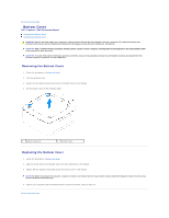
Back to Contents Page Bottom Cover Dell™ Inspiron™ 300/400 Service Manual Removing the Bottom Cover Replacing the Bottom Cover WARNING: Before working inside your computer, read the safety information that shipped with your computer. For additional - Dell Inspiron Zino HD 400 | Inspiron Zino HD Service Manual - Page 5
- Dell Inspiron Zino HD 400 | Inspiron Zino HD Service Manual - Page 6
Back to Contents Page Wireless Mini-Card (Inspiron 400 Only) Dell™ Inspiron™ 300/400 Service Manual Removing the Mini-Card Replacing the Mini-Card WARNING: Before working inside your computer, read the safety information that shipped with your computer. For additional - Dell Inspiron Zino HD 400 | Inspiron Zino HD Service Manual - Page 7
table provides the antenna cable color scheme for the Mini- Card supported by your computer. Connectors on the Mini-Card Antenna Cable Color ) black 6. Replace the drive bay (see Replacing the Drive Bay). 7. Replace the optical drive (see Replacing the Optical Drive). 8. Replace the top bracket - Dell Inspiron Zino HD 400 | Inspiron Zino HD Service Manual - Page 8
Dell™ Inspiron™ 300/400 Service Manual instructions. CAUTION: Only a certified service technician should perform repairs on your computer. Damage due to servicing that is not authorized by Dell the optical drive (see Removing the Optical Drive). 6. Remove the drive bay (see Removing the Drive Bay). 7. - Dell Inspiron Zino HD 400 | Inspiron Zino HD Service Manual - Page 9
5. Replace the top bracket (see Replacing the Top Bracket). 6. Replace the top cover (see Replacing the Top Cover). CAUTION: Before turning on the computer, replace all screws and ensure that no stray screws remain inside the computer. Failure to do so may result in damage to the computer. 7. - Dell Inspiron Zino HD 400 | Inspiron Zino HD Service Manual - Page 10
Back to Contents Page Graphics Card (Inspiron 400 Only) Dell™ Inspiron™ 300/400 Service Manual Removing the Graphics Card Replacing the Graphics Card WARNING: Before working inside your computer, read the safety information that shipped with your computer. For additional - Dell Inspiron Zino HD 400 | Inspiron Zino HD Service Manual - Page 11
7. Connect your computer and all attached devices to electrical outlets, and turn them on. Back to Contents Page - Dell Inspiron Zino HD 400 | Inspiron Zino HD Service Manual - Page 12
Back to Contents Page Graphics-Card Fan (Inspiron 400 Only) Dell™ Inspiron™ 300/400 Service Manual Removing the Graphics-Card Fan Replacing the Graphics-Card Fan WARNING: Before working inside your computer, read the safety information that shipped with your computer. - Dell Inspiron Zino HD 400 | Inspiron Zino HD Service Manual - Page 13
- Dell Inspiron Zino HD 400 | Inspiron Zino HD Service Manual - Page 14
Contents Page Graphics-Card Heat Sink (Inspiron 400 Only) Dell™ Inspiron™ 300/400 Service Manual Removing the Graphics-Card Heat Sink these steps incorrectly could damage your system board. For technical service information, see the Setup Guide. Removing the Graphics-Card Heat Sink 1. Follow the - Dell Inspiron Zino HD 400 | Inspiron Zino HD Service Manual - Page 15
Back to Contents Page - Dell Inspiron Zino HD 400 | Inspiron Zino HD Service Manual - Page 16
Back to Contents Page Hard Drive Dell™ Inspiron™ 300/400 Service Manual Removing the Hard Drive Replacing the Hard Drive WARNING: Before working inside your computer, read the safety information that shipped with your computer. For additional safety best practices information, see the Regulatory - Dell Inspiron Zino HD 400 | Inspiron Zino HD Service Manual - Page 17
for storing or shipping the hard drive. 3. Align the screw holes on the drive bay with the screw holes on the hard drive. 4. Replace the four screws that secure the hard drive to the drive bay. 5. Replace the drive bay (see Replacing the Drive Bay). 6. Replace the optical drive (see Replacing the - Dell Inspiron Zino HD 400 | Inspiron Zino HD Service Manual - Page 18
Back to Contents Page Drive Bay Dell™ Inspiron™ 300/400 Service Manual Removing the Drive Bay Replacing the Drive Bay WARNING: Before working inside your computer, read the safety information that shipped with your computer. For additional safety best practices information, see the Regulatory - Dell Inspiron Zino HD 400 | Inspiron Zino HD Service Manual - Page 19
bay to the system board. 5. Replace the screw that secures the power-button bracket to the drive bay (see Replacing the Power-Button Bracket). 6. Replace the optical drive (see Replacing the Optical Drive). 7. Replace the top bracket (see Replacing the Top Bracket). 8. Replace the top cover (see - Dell Inspiron Zino HD 400 | Inspiron Zino HD Service Manual - Page 20
Back to Contents Page Processor Heat Sink (Inspiron 400 Only) Dell™ Inspiron™ 300/400 Service Manual Removing the Processor Heat Sink Replacing the Processor Heat Sink WARNING: Before working inside your computer, read the safety information that shipped with your computer. - Dell Inspiron Zino HD 400 | Inspiron Zino HD Service Manual - Page 21
the screw holes on the system board and tighten the screws in ascending order. 5. Replace the drive bay (see Replacing the Drive Bay). 6. Replace the optical drive (see Replacing the Optical Drive). 7. Replace the top bracket (see Replacing the Top Bracket). 8. Replace the top cover (see Replacing - Dell Inspiron Zino HD 400 | Inspiron Zino HD Service Manual - Page 22
Back to Contents Page I/O Bracket Dell™ Inspiron™ 300/400 Service Manual Removing the I/O Bracket Replacing the I/O Bezel). 5. Remove the chassis fan (see Removing the Chassis Fan). 6. Using a hex nut driver, remove the two screws that secure the VGA connector to the I/O bracket. 7. Remove the screw - Dell Inspiron Zino HD 400 | Inspiron Zino HD Service Manual - Page 23
4. Using a hex nut driver, replace the two screws that secure the VGA connector to the I/O bracket. 5. Replace the chassis fan (see Replacing the Chassis Fan). 6. Replace the I/O bezel (see - Dell Inspiron Zino HD 400 | Inspiron Zino HD Service Manual - Page 24
Back to Contents Page I/O Bezel Dell™ Inspiron™ 300/400 Service Manual Removing the I/O Bezel Replacing the I/O Bezel WARNING: Before working inside your computer, read the safety information that shipped with your computer. For additional safety best - Dell Inspiron Zino HD 400 | Inspiron Zino HD Service Manual - Page 25
Back to Contents Page - Dell Inspiron Zino HD 400 | Inspiron Zino HD Service Manual - Page 26
Contents Page Memory Module(s) Dell™ Inspiron™ 300/400 Service Manual Inspiron 300 Inspiron 400 WARNING: drive (see Removing the Optical Drive). 5. Remove the drive bay (see Removing the Drive Bay). CAUTION: To prevent damage to the memory module connector, do not use tools to spread the memory - Dell Inspiron Zino HD 400 | Inspiron Zino HD Service Manual - Page 27
: Windows® XP: Click Start® Control Panel® System. Windows Vista®: Click the Start button Windows 7: ® Control Panel® System and Maintenance. Click the Start button ® Control Panel® System and Security® System. 11. Check the amount of memory (RAM) listed. Inspiron 400 Removing the Memory Module - Dell Inspiron Zino HD 400 | Inspiron Zino HD Service Manual - Page 28
that the memory is installed correctly: Windows® XP: Click Start® Control Panel® System. Windows Vista®: Click the Start button Windows 7: ® Control Panel® System and Maintenance. Click the Start button ® Control Panel® System and Security® System. 8. Check the amount of memory (RAM) listed - Dell Inspiron Zino HD 400 | Inspiron Zino HD Service Manual - Page 29
Back to Contents Page Optical Drive Dell™ Inspiron™ 300/400 Service Manual Removing the Optical Drive Replacing the Optical Drive WARNING: Before working inside your computer, read the safety information that shipped with your computer. For additional safety best practices information, see the - Dell Inspiron Zino HD 400 | Inspiron Zino HD Service Manual - Page 30
5. Replace the top bracket (see Replacing the Top Bracket). 6. Replace the top cover (see Replacing the Top Cover). CAUTION: Before turning on the computer, replace all screws and ensure that no stray screws remain inside the computer. Failure to do so may result in damage to the computer. 7. - Dell Inspiron Zino HD 400 | Inspiron Zino HD Service Manual - Page 31
Back to Contents Page Processor (Inspiron 400 Only) Dell™ Inspiron™ 300/400 Service Manual Removing the Processor Replacing the the Top Bracket). 4. Remove the optical drive (see Removing the Optical Drive). 5. Remove the drive bay (see Removing the Drive Bay). 6. Remove the processor heat sink - Dell Inspiron Zino HD 400 | Inspiron Zino HD Service Manual - Page 32
. 6. Align the pin-1 corners of the processor and processor socket. 7. Place the processor lightly in the processor socket and ensure that the processor is positioned correctly. 8. Pivot the processor heat sink (see Replacing the Processor Heat Sink). 12. Replace the drive bay (see Replacing the - Dell Inspiron Zino HD 400 | Inspiron Zino HD Service Manual - Page 33
13. Replace the optical drive (see Replacing the Optical Drive). 14. Replace the top bracket (see Replacing the Top Bracket). 15. Replace the top cover (see Replacing the Top Cover). CAUTION: Before turning on the - Dell Inspiron Zino HD 400 | Inspiron Zino HD Service Manual - Page 34
Back to Contents Page Power-Button Bracket Dell™ Inspiron™ 300/400 Service Manual Removing the Power-Button Bracket Replacing the Power-Button Bracket WARNING: Before working inside your computer, read the safety information that shipped with your computer. For additional safety best practices - Dell Inspiron Zino HD 400 | Inspiron Zino HD Service Manual - Page 35
5. Replace the optical drive (see Replacing the Optical Drive). 6. Replace the top bracket (see Replacing the Top Bracket). 7. Replace the top cover (see Replacing the Top Cover). CAUTION: Before turning on the computer, replace - Dell Inspiron Zino HD 400 | Inspiron Zino HD Service Manual - Page 36
Back to Contents Page Chassis Fan Dell™ Inspiron™ 300/400 Service Manual Removing the Chassis Fan Replacing the Chassis Fan WARNING: Before working inside your computer, read the safety information that shipped with your computer. For additional - Dell Inspiron Zino HD 400 | Inspiron Zino HD Service Manual - Page 37
3. Replace the four screws that secure the chassis fan to the I/O bracket. 4. Connect the chassis fan cable to the connector on the system board. 5. Replace the I/O bezel (see Replacing the I/O Bezel). 6. Replace the top bracket (see Replacing the Top Bracket). 7. Replace the top cover (see - Dell Inspiron Zino HD 400 | Inspiron Zino HD Service Manual - Page 38
Back to Contents Page System Board Dell™ Inspiron™ 300/400 Service Manual Removing the System Board Replacing the System Board Entering the Service Tag in the BIOS WARNING: Before working inside your computer, read the safety information that shipped with your computer. For additional safety best - Dell Inspiron Zino HD 400 | Inspiron Zino HD Service Manual - Page 39
on the chassis and slide the system board in place. 3. Replace the four screws that secure the system board to the chassis. 4. For Inspiron 400 Only: a. Replace the graphics-card fan (see Replacing the Graphics-Card Fan). b. Replace the graphics card (see Replacing the Graphics Card). c. Replace the - Dell Inspiron Zino HD 400 | Inspiron Zino HD Service Manual - Page 40
the computer. NOTE: After you have replaced the system board, enter the computer's Service Tag into the BIOS of the replacement system board. 17. Enter the Service Tag (see Entering the Service Tag in the BIOS). Entering the Service Tag in the BIOS 1. Turn on the computer. 2. Press during POST - Dell Inspiron Zino HD 400 | Inspiron Zino HD Service Manual - Page 41
Dell™ Inspiron™ 300/400 Service Manual password l Read the current amount of memory or set the type of hard drive installed CAUTION: Unless you are an window. The field is a scrollable list containing features that define the configuration of your computer, including installed hardware, power - Dell Inspiron Zino HD 400 | Inspiron Zino HD Service Manual - Page 42
when "USB Controller" is enabled)-FullSpeed or HiSpeed (HiSpeed by default) On or Off (On by default) Enabled or Disabled (Enabled by default) Power Management ACPI Suspend Type AC Recovery Low Power Mode (applicable for Inspiron 400 computer only) Remote Wake Up Auto Power On Auto Power On Date - Dell Inspiron Zino HD 400 | Inspiron Zino HD Service Manual - Page 43
Hard Drive - The computer attempts to boot from the primary hard drive. If no operating system is on the drive, the computer generates an error message. l USB Flash Device - Insert the memory DVD drive to run the Dell Diagnostics on the Drivers and you see the Microsoft Windows desktop. Then shut down - Dell Inspiron Zino HD 400 | Inspiron Zino HD Service Manual - Page 44
section, follow the safety instructions that shipped with your computer service technician should perform repairs on your computer. Damage due to servicing that is not authorized by Dell optical drive (see Removing the Optical Drive). 5. Remove the drive bay (see Removing the Drive Bay Inspiron 300 - Dell Inspiron Zino HD 400 | Inspiron Zino HD Service Manual - Page 45
Inspiron 400 10. Replace the drive bay (see Replacing the Drive Bay). 11. Replace the optical drive (see Replacing the Optical Drive). to the Dell Support website at support.dell.com. 3. Click Drivers & Downloads® Select Model. 4. Locate the BIOS update file for your computer: NOTE: The Service Tag - Dell Inspiron Zino HD 400 | Inspiron Zino HD Service Manual - Page 46
8. Click Close if the Download Complete window appears. The file icon appears on your desktop and is titled the same as the downloaded BIOS update file. 9. Double-click the file icon on the desktop and follow the instructions on the screen. Back to Contents Page - Dell Inspiron Zino HD 400 | Inspiron Zino HD Service Manual - Page 47
Back to Contents Page Technical Overview Dell™ Inspiron™ 300/400 Service Manual Inspiron™ 300 Inspiron 400 WARNING: Before working inside your as a connector on your computer). Inspiron™ 300 Inside View 1 chassis fan 3 drive bay 2 coin-cell battery 4 optical drive System Board Components - Dell Inspiron Zino HD 400 | Inspiron Zino HD Service Manual - Page 48
socket (BAT1) 3 SATA drive connector (SATA2) 4 SATA drive connector (SATA1) 5 optical drive power connector (ODD_PWR1) 6 CMOS jumper (CMOS1) 7 memory-module connector (DIMM1) 8 processor 9 chassis fan connector (SYSFAN1) Inspiron 400 Inside View 1 chassis fan 3 drive bay 5 processor heat - Dell Inspiron Zino HD 400 | Inspiron Zino HD Service Manual - Page 49
1 processor socket 2 processor 3 chassis fan connector (CPU_FAN) 4 SATA power connector (SATAPWR1) 5 CMOS jumper (JP1) 6 coin-cell battery socket (BT1) 7 SATA drive connector (SATA2) 8 SATA drive connector (SATA1) 9 SATA power connector (SATAPWR2) Back to Contents Page - Dell Inspiron Zino HD 400 | Inspiron Zino HD Service Manual - Page 50
to Contents Page Dell™ Inspiron™ 300/400 Service Manual NOTE: A NOTE indicates important information that helps you make better use of your computer. CAUTION: A CAUTION indicates either potential damage to hardware or loss of data and tells you how to avoid the problem. WARNING: A WARNING indicates - Dell Inspiron Zino HD 400 | Inspiron Zino HD Service Manual - Page 51
Back to Contents Page Top Bracket Dell™ Inspiron™ 300/400 Service Manual Removing the Top Bracket Replacing the Top Bracket WARNING: Before working inside your computer, read the safety information that shipped with your computer. For additional - Dell Inspiron Zino HD 400 | Inspiron Zino HD Service Manual - Page 52
top bracket with the slots on the chassis and place the top bracket. 3. Replace the screw that secures the top bracket to the computer. 4. Inspiron 400 - Align the screw holes on the wireless antennas with the screw holes on the top bracket. Replace the two screws that secure the wireless antennas - Dell Inspiron Zino HD 400 | Inspiron Zino HD Service Manual - Page 53
Back to Contents Page Top Cover Dell™ Inspiron™ 300/400 Service Manual Removing the Top Cover Replacing the Top Cover WARNING: Before working inside your computer, read the safety information that shipped with your computer. For additional
-
 1
1 -
 2
2 -
 3
3 -
 4
4 -
 5
5 -
 6
6 -
 7
7 -
8
-
9
-
10
-
11
-
12
-
13
-
14
-
15
-
16
-
17
-
18
-
19
-
20
-
21
-
22
-
23
-
24
-
25
-
26
-
27
-
28
-
29
-
30
-
31
-
32
-
33
-
34
-
35
-
36
-
37
-
38
-
39
-
40
-
41
-
42
-
43
-
44
-
45
-
46
-
47
-
48
-
49
-
50
-
51
-
52
-
53
 |
 |
Dell™ Inspiron™ 300/400 Service Manual
Notes, Cautions, and Warnings
Information in this document is subject to change without notice.
© 2009 Dell Inc. All rights reserved.
Reproduction of these materials in any manner whatsoever without the written permission of Dell Inc. is strictly forbidden.
Trademarks used in this text:
Dell
, the
DELL
logo, and
Inspiron
are trademarks of Dell Inc.;
Microsoft
,
Windows
,
Windows Vista
, and
Windows Vista
start button logo are either
trademarks or registered trademarks of Microsoft Corporation in the United States and/or other countries.
Other trademarks and trade names may be used in this document to refer to either the entities claiming the marks and names or their products. Dell Inc. disclaims any
proprietary interest in trademarks and trade names other than its own.
Regulatory Model D02U series
Regulatory Type D02U001 and D02U002
September 2009
Rev. A00
Technical Overview
Before You Begin
Top Cover
Bottom Cover
Top Bracket
I/O Bezel
Optical Drive
Drive Bay
Power
-
Button Bracket
Coin
-
Cell Battery
Hard Drive
Wireless Mini
-
Card (Inspiron 400 Only)
Memory Module(s)
Processor Heat Sink (Inspiron 400 Only)
Processor (Inspiron 400 Only)
Chassis Fan
I/O Bracket
Graphics
-
Card Heat Sink (Inspiron 400 Only)
Graphics Card (Inspiron 400 Only)
Graphics
-
Card Fan (Inspiron 400 Only)
System Board
System Setup Utility
NOTE:
A NOTE indicates important information that helps you make better use of your computer.
CAUTION:
A CAUTION indicates either potential damage to hardware or loss of data and tells you how to avoid the problem.
WARNING:
A WARNING indicates a potential for property damage, personal injury, or death.