Dell Inspiron Zino HD 400 Inspiron Zino HD Service Manual - Page 27
Inspiron 400 - ram
 |
View all Dell Inspiron Zino HD 400 manuals
Add to My Manuals
Save this manual to your list of manuals |
Page 27 highlights
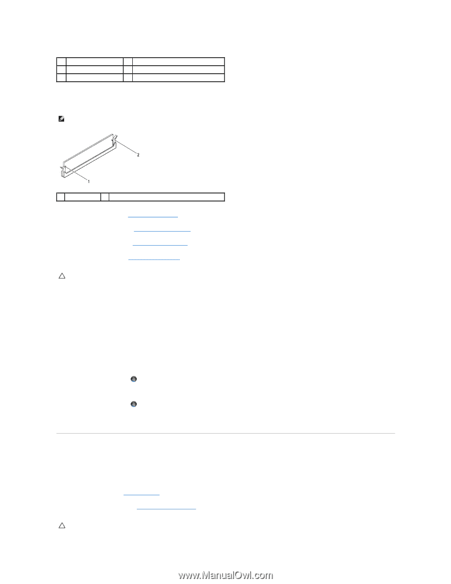
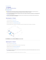
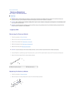
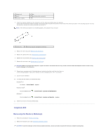
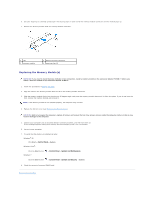
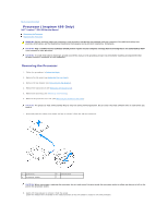
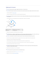
1 cutouts (2) 3 notch 5 memory module 2 tab 4 memory-module connector 3. Insert the memory module into the connector until the memory module snaps into position. If you insert the memory module correctly, the securing clips snap into the cutouts at each end of the memory module. If the securing clips do not snap into position, remove the memory module and reinstall it. NOTE: If the memory module is not installed properly, the computer may not boot. 1 cutouts (2) 2 securing clips (2) (snapped in position) 4. Replace the drive bay (see Replacing the Drive Bay). 5. Replace the optical drive (see Replacing the Optical Drive). 6. Replace the top bracket (see Replacing the Top Bracket). 7. Replace the top cover (see Replacing the Top Cover). CAUTION: Before turning on the computer, replace all screws and ensure that no stray screws remain inside the computer. Failure to do so may result in damage to the computer. 8. Connect your computer and all attached devices to electrical outlets, and then turn them on. If the message appears stating that memory size has changed, press to continue. 9. Log on to your computer. 10. To verify that the memory is installed correctly: Windows® XP: Click Start® Control Panel® System. Windows Vista®: Click the Start button Windows 7: ® Control Panel® System and Maintenance. Click the Start button ® Control Panel® System and Security® System. 11. Check the amount of memory (RAM) listed. Inspiron 400 Removing the Memory Module(s) 1. Follow the procedures in Before You Begin. 2. Remove the bottom cover (see Removing the Bottom Cover). CAUTION: To prevent damage to the memory module connector, do not use tools to spread the memory module securing clips.
-
 1
1 -
2
-
3
-
4
-
5
-
6
-
7
-
8
-
9
-
10
-
11
-
12
-
13
-
14
-
15
-
16
-
17
-
18
-
19
-
20
-
21
-
 22
22 -
 23
23 -
 24
24 -
 25
25 -
 26
26 -
 27
27 -
 28
28 -
 29
29 -
 30
30 -
 31
31 -
 32
32 -
33
-
34
-
35
-
36
-
37
-
38
-
39
-
40
-
41
-
42
-
43
-
44
-
45
-
46
-
47
-
48
-
49
-
50
-
51
-
52
-
53
 |
 |