Dell Inspiron Zino HD 400 Inspiron Zino HD Service Manual - Page 38
System Board
 |
View all Dell Inspiron Zino HD 400 manuals
Add to My Manuals
Save this manual to your list of manuals |
Page 38 highlights
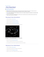
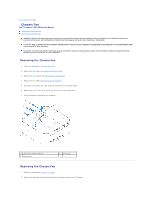
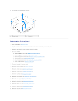
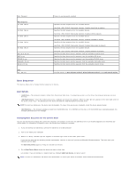
Back to Contents Page System Board Dell™ Inspiron™ 300/400 Service Manual Removing the System Board Replacing the System Board Entering the Service Tag in the BIOS WARNING: Before working inside your computer, read the safety information that shipped with your computer. For additional safety best practices information, see the Regulatory Compliance Homepage at www.dell.com/regulatory_compliance. CAUTION: Only a certified service technician should perform repairs on your computer. Damage due to servicing that is not authorized by Dell™ is not covered by your warranty. CAUTION: To avoid electrostatic discharge, ground yourself by using a wrist grounding strap or by periodically touching an unpainted metal surface (such as a connector on your computer). CAUTION: Handle components and cards by their edges, and avoid touching pins and contacts. The system board's BIOS chip contains the Service Tag, which is also visible on a barcode label on the computer. The replacement kit for the system board includes a CD that provides a utility for transferring the Service Tag to the replacement system board. Removing the System Board 1. Follow the procedures in Before You Begin. 2. Remove the top cover (see Removing the Top Cover). 3. Remove the top bracket (see Removing the Top Bracket). 4. Remove the bottom cover (see Removing the Bottom Cover). 5. Remove the optical drive (see Removing the Optical Drive). 6. Remove the drive bay (see Removing the Drive Bay). 7. Remove the coin-cell battery (see Removing the Coin-Cell Battery). 8. Remove the I/O bezel (see Removing the I/O Bezel). 9. Remove the chassis fan (see Removing the Chassis Fan). 10. Remove the I/O bracket (see Removing the I/O Bracket). 11. Remove the memory module(s) (see Memory Module(s)). 12. For Inspiron 400 Only: a. Remove the Mini-Card (see Removing the Mini-Card). b. Remove the processor heat sink (see Removing the Processor Heat Sink). c. Remove the processor (see Removing the Processor). NOTE: Make note of the cable routing before disconnecting the cables from the system board. d. Remove the graphics-card heat sink (see Removing the Graphics-Card Heat Sink). e. Remove the graphics card (see Removing the Graphics Card). f. Remove the graphics-card fan (see Removing the Graphics-Card Fan). 13. Disconnect all the cables connected to the system board. 14. Remove the four screws that secure the system board to the chassis. 15. Push the system board from the bottom to release the system board from the chassis. 16. Slide the system board to the back of the chassis to release the connectors on the system board from the slots on the chassis.
-
 1
1 -
2
-
3
-
4
-
5
-
6
-
7
-
8
-
9
-
10
-
11
-
12
-
13
-
14
-
15
-
16
-
17
-
18
-
19
-
20
-
21
-
22
-
23
-
24
-
25
-
26
-
27
-
28
-
29
-
30
-
31
-
32
-
 33
33 -
 34
34 -
 35
35 -
 36
36 -
 37
37 -
 38
38 -
 39
39 -
 40
40 -
 41
41 -
 42
42 -
 43
43 -
44
-
45
-
46
-
47
-
48
-
49
-
50
-
51
-
52
-
53
 |
 |