Dell Inspiron Zino HD 400 Inspiron Zino HD Service Manual - Page 22
I/O Bracket
 |
View all Dell Inspiron Zino HD 400 manuals
Add to My Manuals
Save this manual to your list of manuals |
Page 22 highlights
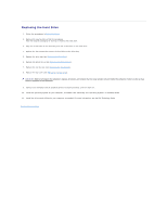
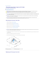
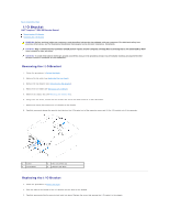
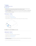
Back to Contents Page I/O Bracket Dell™ Inspiron™ 300/400 Service Manual Removing the I/O Bracket Replacing the I/O Bracket WARNING: Before working inside your computer, read the safety information that shipped with your computer. For additional safety best practices information, see the Regulatory Compliance Homepage at www.dell.com/regulatory_compliance. CAUTION: Only a certified service technician should perform repairs on your computer. Damage due to servicing that is not authorized by Dell™ is not covered by your warranty. CAUTION: To avoid electrostatic discharge, ground yourself by using a wrist grounding strap or by periodically touching an unpainted metal surface (such as a connector on your computer). Removing the I/O Bracket 1. Follow the procedures in Before You Begin. 2. Remove the top cover (see Removing the Top Cover). 3. Remove the top bracket (see Removing the Top Bracket). 4. Remove the I/O bezel (see Removing the I/O Bezel). 5. Remove the chassis fan (see Removing the Chassis Fan). 6. Using a hex nut driver, remove the two screws that secure the VGA connector to the I/O bracket. 7. Remove the screw that secures the I/O bracket to the chassis. 8. Carefully press and release the security lock latch on the I/O bracket out of the computer cover and lift the I/O bracket out of the computer. 1 screw 3 I/O bracket 2 hex nut screws (2) 4 security lock latch Replacing the I/O Bracket 1. Follow the procedures in Before You Begin. 2. Slide the tabs on the bottom of the I/O bracket into the slots on the chassis. 3. Carefully press and slide the security lock latch into place. Replace the screw that secures the I/O bracket to the chassis.
-
 1
1 -
2
-
3
-
4
-
5
-
6
-
7
-
8
-
9
-
10
-
11
-
12
-
13
-
14
-
15
-
16
-
 17
17 -
 18
18 -
 19
19 -
 20
20 -
 21
21 -
 22
22 -
 23
23 -
 24
24 -
 25
25 -
 26
26 -
 27
27 -
28
-
29
-
30
-
31
-
32
-
33
-
34
-
35
-
36
-
37
-
38
-
39
-
40
-
41
-
42
-
43
-
44
-
45
-
46
-
47
-
48
-
49
-
50
-
51
-
52
-
53
 |
 |