Dell Latitude LS Service Manual - Page 19
Tighten the two screws that you installed in step 6.
 |
View all Dell Latitude LS manuals
Add to My Manuals
Save this manual to your list of manuals |
Page 19 highlights
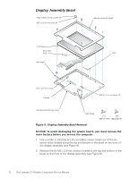
6. Reinstall the two M2 x 4-mm screws that secure the display assembly to the bottom case. You may have to squeeze the display assembly and the bottom assembly together, so the screw holes align in the base assembly and the hinge posts. Do not completely tighten the screws. 7. Reinstall the two M2 x 4-mm screws in the back of the computer that secure the display assembly to the back of the bottom case. 8. Tighten the two screws that you installed in step 6. 9. Open the display and reinstall the left and right hinge covers. An L is stamped on the bottom of the left hinge cover and an R is stamped on the bottom of the right hinge cover. support.dell.com Dell Latitude LS Portable Computers Service Manual 11
-
 1
1 -
2
-
3
-
4
-
5
-
6
-
7
-
8
-
9
-
10
-
11
-
12
-
13
-
 14
14 -
 15
15 -
 16
16 -
 17
17 -
 18
18 -
 19
19 -
 20
20 -
 21
21 -
 22
22 -
 23
23 -
 24
24 -
25
-
26
-
27
-
28
-
29
-
30
-
31
-
32
-
33
-
34
-
35
-
36
-
37
-
38
-
39
-
40
-
41
-
42
-
43
-
44
-
45
-
46
-
47
-
48
 |
 |

support.dell.com
Dell Latitude LS Portable Computers Service Manual
11
6.
Reinstall the two M2 x 4-mm screws that secure the display assembly to
the bottom case.
You may have to squeeze the display assembly and the bottom assembly
together, so the screw holes align in the base assembly and the hinge
posts.
Do not completely tighten the screws.
7.
Reinstall the two M2 x 4-mm screws in the back of the computer that
secure the display assembly to the back of the bottom case.
8.
Tighten the two screws that you installed in step 6.
9.
Open the display and reinstall the left and right hinge covers.
An
L
is stamped on the bottom of the left hinge cover and an
R
is stamped
on the bottom of the right hinge cover.