Dell Latitude LS Service Manual - Page 38
System Board Assembly
 |
View all Dell Latitude LS manuals
Add to My Manuals
Save this manual to your list of manuals |
Page 38 highlights
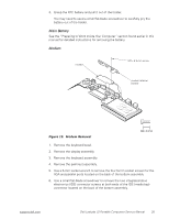
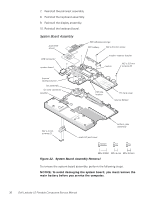
7. Reinstall the palmrest assembly. 8. Reinstall the keyboard assembly. 9. Reinstall the display assembly. 10. Reinstall the keyboard bezel. System Board Assembly 6 audio EMI shield EMI adhesive sponge RTC battery M2 x 8.5-mm screw USB connector system board modem retainer bracket modem M2 x 3.5-mm screws (6) thermal cooling solution fan assembly fan wire connector speaker EMI clip location PC Card cover reserve battery M2 x 4-mm screws (2) audio I/O port cover bottom case assembly Figure 22. System Board Assembly Removal To remove the system board assembly, perform the following steps. NOTICE: To avoid damaging the system board, you must remove the main battery before you service the computer. 30 Dell Latitude LS Portable Computers Service Manual
-
 1
1 -
2
-
3
-
4
-
5
-
6
-
7
-
8
-
9
-
10
-
11
-
12
-
13
-
14
-
15
-
16
-
17
-
18
-
19
-
20
-
21
-
22
-
23
-
24
-
25
-
26
-
27
-
28
-
29
-
30
-
31
-
32
-
 33
33 -
 34
34 -
 35
35 -
 36
36 -
 37
37 -
 38
38 -
 39
39 -
 40
40 -
 41
41 -
 42
42 -
 43
43 -
44
-
45
-
46
-
47
-
48
 |
 |
