Dell Latitude LS Service Manual - Page 29
Removing the Palmrest Assembly Top Screws
 |
View all Dell Latitude LS manuals
Add to My Manuals
Save this manual to your list of manuals |
Page 29 highlights
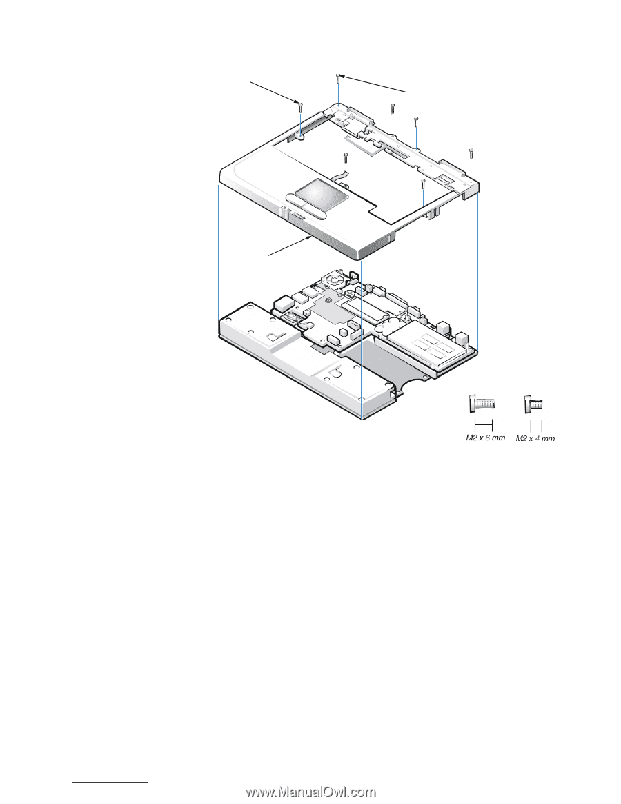
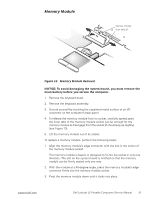
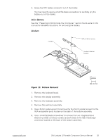
M2 x 6-mm screws (3 silver) M2 x 4-mm screws (4 black) palmrest assembly Figure 15. Removing the Palmrest Assembly Top Screws 8. Remove the three silver M2 x 6-mm screws in the keyboard-assembly area that secure the middle of the palmrest assembly to the bottom case (see Figure 15). 9. Disconnect the status lights flex cable from the ZIF connector on the system board. 10. Disconnect the touch pad flex cable from the ZIF connector on the system board. 11. Carefully remove the palmrest assembly from the bottom assembly. To replace the palmrest assembly, perform the following steps: 1. Place the palmrest assembly on the bottom assembly. 2. Reinstall the three silver M2 x 6-mm screws in the keyboard-assembly area that secure the middle of the palmrest assembly to the bottom-case assembly (see Figure 15). support.dell.com Dell Latitude LS Portable Computers Service Manual 21
-
 1
1 -
2
-
3
-
4
-
5
-
6
-
7
-
8
-
9
-
10
-
11
-
12
-
13
-
14
-
15
-
16
-
17
-
18
-
19
-
20
-
21
-
22
-
23
-
 24
24 -
 25
25 -
 26
26 -
 27
27 -
 28
28 -
 29
29 -
 30
30 -
 31
31 -
 32
32 -
 33
33 -
 34
34 -
35
-
36
-
37
-
38
-
39
-
40
-
41
-
42
-
43
-
44
-
45
-
46
-
47
-
48
 |
 |