Dell Latitude LS Service Manual - Page 25
Keyboard Assembly
 |
View all Dell Latitude LS manuals
Add to My Manuals
Save this manual to your list of manuals |
Page 25 highlights
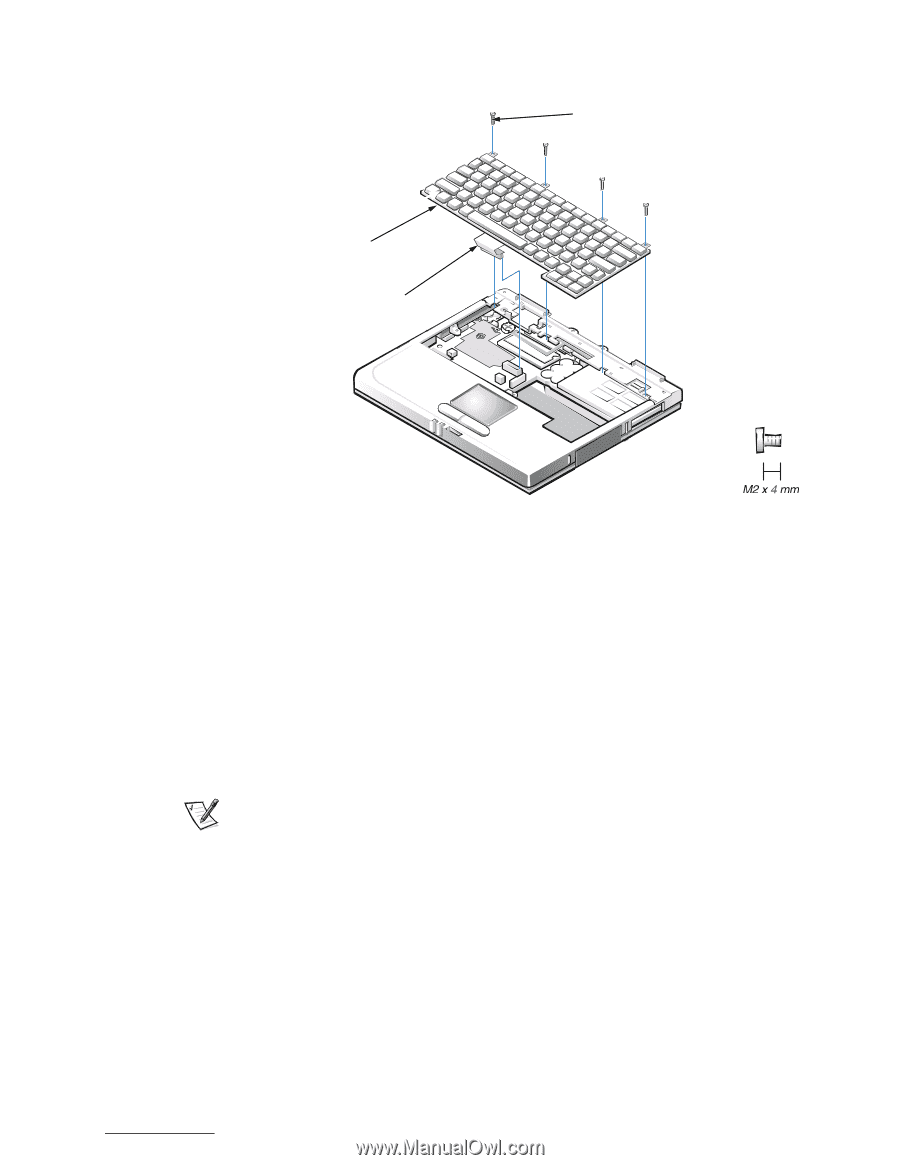
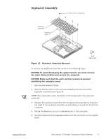
Keyboard Assembly M2 x 4-mm screws (4) keyboard assembly keyboard cable Figure 12. Keyboard Assembly Removal To remove the keyboard assembly, perform the following steps. NOTICE: To avoid damaging the system board, you must remove the main battery before you service the computer. NOTICE: Make sure that the work surface is clean to prevent scratching the computer cover. 1. Remove the keyboard bezel. 2. Remove the four M2 x 4-mm screws located across the top of the keyboard assembly (see Figure 9). NOTE: Five metal tabs retain the bottom of the keyboard in the palmrest assembly. 3. Release the keyboard assembly from the palmrest assembly by lifting the top edge of the keyboard assembly up and sliding it toward the back of the computer. 4. Rotate the keyboard up so it is perpendicular to the computer. 5. Carefully disconnect the keyboard cable from the connector on the system board. support.dell.com Dell Latitude LS Portable Computers Service Manual 17
-
 1
1 -
2
-
3
-
4
-
5
-
6
-
7
-
8
-
9
-
10
-
11
-
12
-
13
-
14
-
15
-
16
-
17
-
18
-
19
-
 20
20 -
 21
21 -
 22
22 -
 23
23 -
 24
24 -
 25
25 -
 26
26 -
 27
27 -
 28
28 -
 29
29 -
 30
30 -
31
-
32
-
33
-
34
-
35
-
36
-
37
-
38
-
39
-
40
-
41
-
42
-
43
-
44
-
45
-
46
-
47
-
48
 |
 |