Dell Latitude LS Service Manual - Page 41
Main Battery Release Latch
 |
View all Dell Latitude LS manuals
Add to My Manuals
Save this manual to your list of manuals |
Page 41 highlights
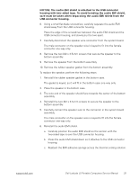
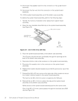
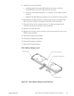
9. Reinstall the audio EMI shield. a. Carefully position the audio EMI shield so the section with the two-sided tape is over the USB connector housing. b. Press the audio EMI shield down so it attaches to the USB connector housing. c. Reattach the EMI adhesive sponge across the thermal cooling solution. 10. Reinstall the two IDE connector screws at both ends of the IDE (media bay) connector located on the back of the bottom case assembly. 11. Reinstall the four 5-mm socket screws for the VGA and parallel ports located on the back of the bottom case assembly 12. Replace the audio I/O cover. 13. Replace the two M2 x 4-mm screws to secure the audio I/O cover to the bottom case assembly. 14. Reinstall the palmrest assembly. 15. Reinstall the keyboard assembly. 16. Reinstall the display assembly. 17. Reinstall the keyboard bezel. Main Battery Release Latch tension spring bottom case assembly main battery release latch release button Figure 24. Main Battery Release Latch Removal support.dell.com Dell Latitude LS Portable Computers Service Manual 33
-
 1
1 -
2
-
3
-
4
-
5
-
6
-
7
-
8
-
9
-
10
-
11
-
12
-
13
-
14
-
15
-
16
-
17
-
18
-
19
-
20
-
21
-
22
-
23
-
24
-
25
-
26
-
27
-
28
-
29
-
30
-
31
-
32
-
33
-
34
-
35
-
 36
36 -
 37
37 -
 38
38 -
 39
39 -
 40
40 -
 41
41 -
 42
42 -
 43
43 -
 44
44 -
 45
45 -
 46
46 -
47
-
48
 |
 |
