Dell Latitude LS Service Manual - Page 39
skin reduce the heat transfer capability on the glue side of the tape.
 |
View all Dell Latitude LS manuals
Add to My Manuals
Save this manual to your list of manuals |
Page 39 highlights
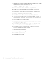
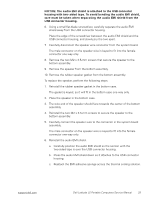
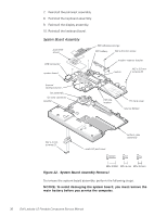
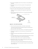
NOTICE: The processor is not replaceable. Do not attempt to remove the thermal cooling solution. 1. Remove the keyboard bezel. 2. Remove the display assembly. 3. Remove the keyboard. 4. Remove the palmrest assembly. 5. Use a 5-mm socket wrench to remove the four 5-mm socket screws for the VGA and parallel ports located on the back of the bottom case assembly. 6. Use a small flat-blade screwdriver to remove the two IDE connector screws at both ends of the IDE (media bay) connector located on the back of the bottom case assembly. NOTICE: To ensure maximum cooling for the microprocessor, do not touch the glue side of the thermal conductive tape. The oils in your skin reduce the heat transfer capability on the glue side of the tape. 7. Peel up the EMI adhesive sponge that connects the audio EMI shield to the thermal cooling solution (see Figure 22). You only need to peel up the part of the sponge that lays on the thermal cooling solution. The end of the sponge that lays on the audio EMI shield can remain. NOTICE: The audio EMI shield is attached to the USB connector housing with two-sided tape. To avoid bending the audio EMI shield, care must be taken when separating the audio EMI shield from the USB connector housing. 8. Using a small flat-blade screwdriver, carefully separate the audio EMI shield away from the USB connector housing. Place the edge of the screwdriver between the audio EMI shield and the USB connector housing, and slowly pry the two apart. 9. Remove the two M2 x 4-mm screws that secure the audio I/O cover to the bottom case assembly. 10. Remove the audio I/O cover. 11. Remove the six M2 x 3.5-mm screws that secure the system board to the bottom case assembly. White arrows on the system board assembly point to the M2 x 3.5-mm screws. 12. Remove the M2 x 8.5-mm screw that secures the modem retainer bracket. 13. Remove the modem retainer bracket from the bottom case assembly. support.dell.com Dell Latitude LS Portable Computers Service Manual 31
-
 1
1 -
2
-
3
-
4
-
5
-
6
-
7
-
8
-
9
-
10
-
11
-
12
-
13
-
14
-
15
-
16
-
17
-
18
-
19
-
20
-
21
-
22
-
23
-
24
-
25
-
26
-
27
-
28
-
29
-
30
-
31
-
32
-
33
-
 34
34 -
 35
35 -
 36
36 -
 37
37 -
 38
38 -
 39
39 -
 40
40 -
 41
41 -
 42
42 -
 43
43 -
 44
44 -
45
-
46
-
47
-
48
 |
 |
