Dell Latitude LS Service Manual - Page 6
s, Table - memory
 |
View all Dell Latitude LS manuals
Add to My Manuals
Save this manual to your list of manuals |
Page 6 highlights
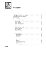
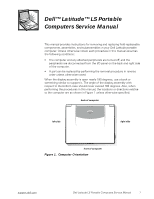
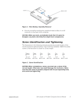
Figures Table Figure 1. Figure 2. Figure 3. Figure 4. Figure 5. Figure 6. Figure 7. Figure 8. Figure 9. Figure 10. Figure 11. Figure 12. Figure 13. Figure 14. Figure 15. Figure 16. Figure 17. Figure 18. Figure 19. Figure 20. Figure 21. Figure 22. Figure 23. Figure 24. Computer Orientation 1 Main Battery Assembly Removal 3 Screw Identification 3 Disconnecting an Interface Cable 5 Exploded View-Computer 6 Hard-Disk Drive Assembly Removal 7 Keyboard Bezel Removal 8 Display Assembly Removal 9 Display Assembly Bezel Removal 12 Display Assembly Latch Removal 13 LCD Panel Removal 14 Keyboard Assembly Removal 17 Memory Module Removal 19 Removing the Palmrest Assembly Bottom Screws 20 Removing the Palmrest Assembly Top Screws 21 Touch Pad Removal 22 Bottom Assembly 23 Reserve Battery Removal 24 Modem Removal 25 Fan Removal 27 Speaker Removal 28 System Board Assembly Removal 30 Hard-Disk Drive EMI Clip 32 Main Battery Release Latch Removal 33 Table 1. Screw Placement Mat with Component Screw Counts and Sizes 4 vi
-
 1
1 -
 2
2 -
 3
3 -
 4
4 -
 5
5 -
 6
6 -
 7
7 -
 8
8 -
 9
9 -
 10
10 -
 11
11 -
 12
12 -
13
-
14
-
15
-
16
-
17
-
18
-
19
-
20
-
21
-
22
-
23
-
24
-
25
-
26
-
27
-
28
-
29
-
30
-
31
-
32
-
33
-
34
-
35
-
36
-
37
-
38
-
39
-
40
-
41
-
42
-
43
-
44
-
45
-
46
-
47
-
48
 |
 |
