Dell Latitude LS Service Manual - Page 20
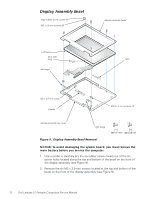
Display Assembly Bezel
 |
View all Dell Latitude LS manuals
Add to My Manuals
Save this manual to your list of manuals |
Page 20 highlights
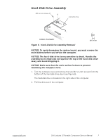
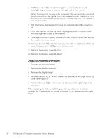
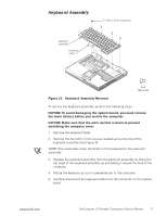
Display Assembly Bezel l large rubber screw covers (6) M2 x 3.5-mm screws (6) display assembly bezel LCD panel back light plug left hinge latch M2 x 3.5-mm screw inverter M2.6 x 4-mm screws (4) display-assembly top cover right hinge Figure 9. Display Assembly Bezel Removal NOTICE: To avoid damaging the system board, you must remove the main battery before you service the computer. 1. Use a scribe to carefully pry the six rubber screw covers out of the six screw holes located along the top and bottom of the bezel on the front of the display assembly (see Figure 9). 2. Remove the six M2 x 3.5-mm screws located at the top and bottom of the bezel on the front of the display assembly (see Figure 9). 12 Dell Latitude LS Portable Computers Service Manual
-
 1
1 -
2
-
3
-
4
-
5
-
6
-
7
-
8
-
9
-
10
-
11
-
12
-
13
-
14
-
 15
15 -
 16
16 -
 17
17 -
 18
18 -
 19
19 -
 20
20 -
 21
21 -
 22
22 -
 23
23 -
 24
24 -
 25
25 -
26
-
27
-
28
-
29
-
30
-
31
-
32
-
33
-
34
-
35
-
36
-
37
-
38
-
39
-
40
-
41
-
42
-
43
-
44
-
45
-
46
-
47
-
48
 |
 |
