Dell Latitude LS Service Manual - Page 31
Bottom Assembly
 |
View all Dell Latitude LS manuals
Add to My Manuals
Save this manual to your list of manuals |
Page 31 highlights
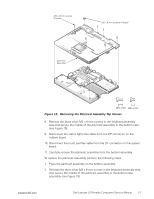
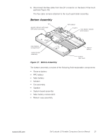
8. Disconnect the flex cable from the ZIF connector on the back of the touch pad (see Figure 16). The flex cable remains attached to the touch pad holder assembly. Bottom Assembly fan speaker (shown with audio EMI shield removed) RTC battery modem main battery release latch location main battery compartment system board assembly Figure 17. Bottom Assembly reserve battery bottom case cover The bottom assembly consists of the following field-replaceable components: • Reserve battery • RTC battery • Main battery • Modem • Fan assembly • Speaker • System board assembly • Main battery release latch • Bottom case assembly support.dell.com Dell Latitude LS Portable Computers Service Manual 23
-
 1
1 -
2
-
3
-
4
-
5
-
6
-
7
-
8
-
9
-
10
-
11
-
12
-
13
-
14
-
15
-
16
-
17
-
18
-
19
-
20
-
21
-
22
-
23
-
24
-
25
-
 26
26 -
 27
27 -
 28
28 -
 29
29 -
 30
30 -
 31
31 -
 32
32 -
 33
33 -
 34
34 -
 35
35 -
 36
36 -
37
-
38
-
39
-
40
-
41
-
42
-
43
-
44
-
45
-
46
-
47
-
48
 |
 |

support.dell.com
Dell Latitude LS Portable Computers Service Manual
23
8.
Disconnect the flex cable from the ZIF connector on the back of the touch
pad (see Figure 16).
The flex cable remains attached to the touch pad holder assembly.
Bottom Assembly
Figure 17.
Bottom Assembly
The bottom assembly consists of the following field-replaceable components:
•
Reserve battery
•
RTC battery
•
Main battery
•
Modem
•
Fan assembly
•
Speaker
•
System board assembly
•
Main battery release latch
•
Bottom case assembly
reserve
battery
fan
main battery
compartment
system board
assembly
bottom
case cover
main battery release
latch location
RTC battery
modem
speaker (shown with audio
EMI shield removed)