Dell Latitude LS Service Manual - Page 40
Hard-Disk Drive EMI Clip
 |
View all Dell Latitude LS manuals
Add to My Manuals
Save this manual to your list of manuals |
Page 40 highlights
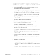
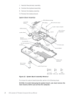
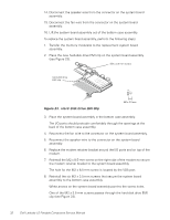
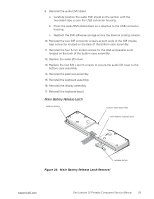
14. Disconnect the speaker wire from the connector on the system board assembly. 15. Disconnect the fan wire from the connector on the system board assembly. 16. Lift the system board assembly out of the bottom case assembly. To replace the system board assembly, perform the following steps: 1. Transfer the memory module(s) to the replacement system board assembly. 2. Place the new hard-disk drive EMI clip on the system board assembly (see Figure 23). M2 x 3.5-mm screw hard-disk drive EMI clip Figure 23. Hard-Disk Drive EMI Clip 3. Place the system board assembly in the bottom case assembly. The I/O ports should protrude comfortably through the openings at the back of the bottom case assembly. 4. Reconnect the fan wire to the connector on the system board assembly. 5. Reconnect the speaker wire to the connector on the system board assembly. 6. Replace the modem retainer bracket around the I/O ports and on top of the modem. 7. Reinstall the M2 x 8.5-mm screw on the right side of the modem to secure the modem retainer bracket to the system board assembly. The hole for the M2 x 8.5-mm screw is located by the VGA port. 8. Reinstall the six M2 x 3.5-mm screws that secure the system board assembly to the bottom case assembly. White arrows on the system board assembly point to the screw holes. One of the M2 x 3.5-mm screws passes through the hard-disk drive EMI clip (see Figure 23). 32 Dell Latitude LS Portable Computers Service Manual
-
 1
1 -
2
-
3
-
4
-
5
-
6
-
7
-
8
-
9
-
10
-
11
-
12
-
13
-
14
-
15
-
16
-
17
-
18
-
19
-
20
-
21
-
22
-
23
-
24
-
25
-
26
-
27
-
28
-
29
-
30
-
31
-
32
-
33
-
34
-
 35
35 -
 36
36 -
 37
37 -
 38
38 -
 39
39 -
 40
40 -
 41
41 -
 42
42 -
 43
43 -
 44
44 -
 45
45 -
46
-
47
-
48
 |
 |
