Dell Latitude XPi Service Manual - Page 105
I/O Board, A-8., I/O Board Removal
 |
View all Dell Latitude XPi manuals
Add to My Manuals
Save this manual to your list of manuals |
Page 105 highlights
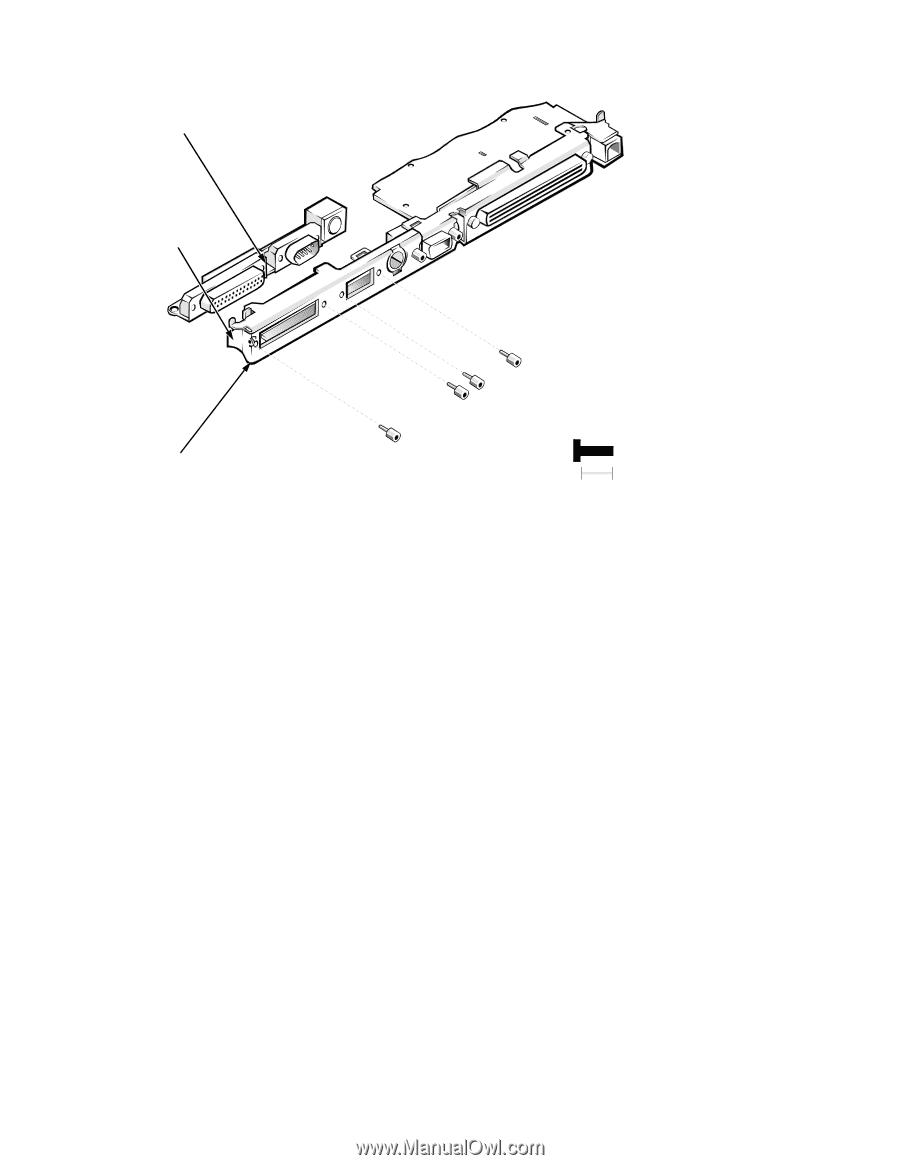
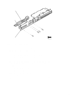
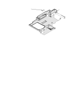
I/O Board I/O board I/O bracket clip ST4 (8 mm) ST3 (8 mm) ST2 (8 mm) I/O bracket ST1 (8 mm) 8 mm Figure A-8. I/O Board Removal To remove and replace the I/O board, follow these steps: 1. Remove the I/O interface cable from connector JSTDIO. See the previous subsection in this appendix. 2. Remove the keyboard/keypad/mouse connector shield. See "Keyboard/Keypad/Mouse Connector Shield" found earlier in this appendix. 3. Remove the four hexagonal standoff screws ST1 through ST4 that secure the serial and parallel port connectors to the I/O panel. Use a 3/16 nut holder to remove the standoff screws. 4. Remove the side I/O bracket clip. See "System Board Assembly" in Chapter 4. 5. Lift the I/O board away from the I/O panel. When replacing the I/O board, make sure that the side I/O bracket clip is positioned so that it rests directly on the I/O board, rather than between the I/O board and I/O bracket (see Figure A-8). Factory Repair Parts A-23
-
 1
1 -
2
-
3
-
4
-
5
-
6
-
7
-
8
-
9
-
10
-
11
-
12
-
13
-
14
-
15
-
16
-
17
-
18
-
19
-
20
-
21
-
22
-
23
-
24
-
25
-
26
-
27
-
28
-
29
-
30
-
31
-
32
-
33
-
34
-
35
-
36
-
37
-
38
-
39
-
40
-
41
-
42
-
43
-
44
-
45
-
46
-
47
-
48
-
49
-
50
-
51
-
52
-
53
-
54
-
55
-
56
-
57
-
58
-
59
-
60
-
61
-
62
-
63
-
64
-
65
-
66
-
67
-
68
-
69
-
70
-
71
-
72
-
73
-
74
-
75
-
76
-
77
-
78
-
79
-
80
-
81
-
82
-
83
-
84
-
85
-
86
-
87
-
88
-
89
-
90
-
91
-
92
-
93
-
94
-
95
-
96
-
97
-
98
-
99
-
 100
100 -
 101
101 -
 102
102 -
 103
103 -
 104
104 -
 105
105 -
 106
106 -
 107
107 -
 108
108 -
 109
109 -
 110
110 -
111
-
112
-
113
-
114
-
115
-
116
-
117
-
118
-
119
-
120
-
121
-
122
 |
 |