Dell Latitude XPi Service Manual - Page 98
CD-ROM Drive, Diskette Drive, Palmrest Assembly Components, Trackball, Trackball Interface Cable
 |
View all Dell Latitude XPi manuals
Add to My Manuals
Save this manual to your list of manuals |
Page 98 highlights
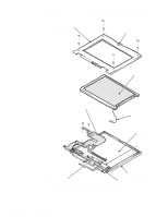
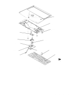
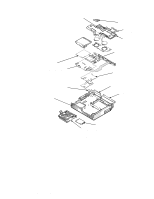
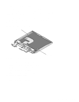
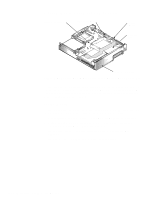
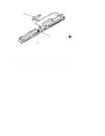
CD-ROM Drive The CD-ROM drive is attached to the CD-ROM/diskette drive bracket. See "Diskette/CD-ROM Drive Assembly" in Chapter 4 for instructions about removing the diskette/CD-ROM assembly from the bottom case assembly. The CD-ROM flex cable is threaded through a slot in the drive bracket. Remove the four screws that hold the CD-ROM to the drive bracket. Slide the CD-ROM flex cable out of the slot in the bracket holding the CD-ROM. The CD-ROM is replaced as a unit and is not disassembled. Diskette Drive The diskette drive is attached to the CD-ROM/diskette drive bracket. See "Diskette/CD-ROM Drive Assembly" in Chapter 4 for instructions about removing the diskette/CD-ROM assembly from the bottom case assembly. Remove three screws to separate the diskette drive from the drive bracket. The diskette drive is replaced as a unit and is not disassembled. Palmrest Assembly Components To remove and replace a component of the palmrest assembly, you must first remove the assembly as described in "Palmrest Assembly" in Chapter 4. The subsections that follow provide removal procedures for the components of the trackball assembly. See Figure A-2. Trackball Turn the trackball board over. Rotate the retaining ring counter-clockwise. Lift the trackball out of the recess in the trackball holder. Trackball Interface Cable Gently disconnect the end of the cable from connector J1 on the trackball button board. Trackball Button Board Remove retaining screw A6 (see Figure A-2), and lift the board out of the palmrest assembly. When replacing the board, fit the two small switches on the underside of the board into the recesses in the palmrest. Palmrest Brace Remove screws A-7 through A-9 (see Figure A-2). Gently pull the brace toward the front, and lift the brace away from the palmrest. A-16 Dell Latitude XPi CD Service Manual
-
 1
1 -
2
-
3
-
4
-
5
-
6
-
7
-
8
-
9
-
10
-
11
-
12
-
13
-
14
-
15
-
16
-
17
-
18
-
19
-
20
-
21
-
22
-
23
-
24
-
25
-
26
-
27
-
28
-
29
-
30
-
31
-
32
-
33
-
34
-
35
-
36
-
37
-
38
-
39
-
40
-
41
-
42
-
43
-
44
-
45
-
46
-
47
-
48
-
49
-
50
-
51
-
52
-
53
-
54
-
55
-
56
-
57
-
58
-
59
-
60
-
61
-
62
-
63
-
64
-
65
-
66
-
67
-
68
-
69
-
70
-
71
-
72
-
73
-
74
-
75
-
76
-
77
-
78
-
79
-
80
-
81
-
82
-
83
-
84
-
85
-
86
-
87
-
88
-
89
-
90
-
91
-
92
-
 93
93 -
 94
94 -
 95
95 -
 96
96 -
 97
97 -
 98
98 -
 99
99 -
 100
100 -
 101
101 -
 102
102 -
 103
103 -
104
-
105
-
106
-
107
-
108
-
109
-
110
-
111
-
112
-
113
-
114
-
115
-
116
-
117
-
118
-
119
-
120
-
121
-
122
 |
 |
