Dell Latitude XPi Service Manual - Page 58
Display Assembly Bezel,
 |
View all Dell Latitude XPi manuals
Add to My Manuals
Save this manual to your list of manuals |
Page 58 highlights
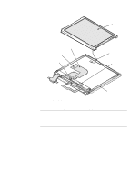
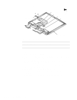
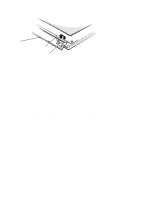
Display Assembly Bezel l display assembly bezel screw covers (4) H2 (10 mm) H1 (10 mm) display assembly base H3 (10 mm) hinge 10 mm H4 (10 mm) Figure 4-15. Display Assembly Bezel Removal Part or Assembly Name Order Name Bezel service kit, 12.1-inch SVC,BZL,LCD,TFT,LXPiCD Display case service kit, 12.1-inch SVC,CVR,BK,TFT,LXPi+ To remove the display assembly bezel, follow these steps: 1. Use a scribe to pry the retaining screw covers out of the screw holes in the bezel. 2. Remove retaining screws H1, H2, H3, and H4. 3. Separate the bezel from the display assembly. Insert your fingertips between the bezel and the LCD, and lift upward on the bezel to release the hidden tabs just above the indicator panel, as well as the hidden tabs beneath each side of the bezel. Then slide the bezel toward the front of the computer, and lift it up and away from the display assembly. When replacing the bezel, orient the bezel in its original position on the display assembly and press firmly near each tab until it snaps into position. Be careful to have the display latch and spring properly assembled. 4-20 Dell Latitude XPi CD Service Manual
-
 1
1 -
2
-
3
-
4
-
5
-
6
-
7
-
8
-
9
-
10
-
11
-
12
-
13
-
14
-
15
-
16
-
17
-
18
-
19
-
20
-
21
-
22
-
23
-
24
-
25
-
26
-
27
-
28
-
29
-
30
-
31
-
32
-
33
-
34
-
35
-
36
-
37
-
38
-
39
-
40
-
41
-
42
-
43
-
44
-
45
-
46
-
47
-
48
-
49
-
50
-
51
-
52
-
 53
53 -
 54
54 -
 55
55 -
 56
56 -
 57
57 -
 58
58 -
 59
59 -
 60
60 -
 61
61 -
 62
62 -
 63
63 -
64
-
65
-
66
-
67
-
68
-
69
-
70
-
71
-
72
-
73
-
74
-
75
-
76
-
77
-
78
-
79
-
80
-
81
-
82
-
83
-
84
-
85
-
86
-
87
-
88
-
89
-
90
-
91
-
92
-
93
-
94
-
95
-
96
-
97
-
98
-
99
-
100
-
101
-
102
-
103
-
104
-
105
-
106
-
107
-
108
-
109
-
110
-
111
-
112
-
113
-
114
-
115
-
116
-
117
-
118
-
119
-
120
-
121
-
122
 |
 |
