Dell Latitude XPi Service Manual - Page 70
cable from the connector; doing so can ruin the cable's electrical
 |
View all Dell Latitude XPi manuals
Add to My Manuals
Save this manual to your list of manuals |
Page 70 highlights
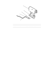
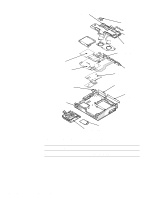
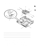
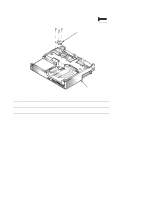
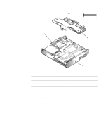
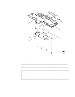
4. Lift the drive assembly straight up about 1 inch. The front edge of the drive assembly engages tabs on the bottom case assembly. Make sure the diskette drive assembly is clear of the tab before attempting to lift it out of the bottom case assembly. CAUTION: Before removing the diskette drive and CD-ROM drive interface cables from connectors JFLOP and JCDROM, release each connector's plastic flip lock (see Figure 4-23). Do not pull the interface cable from the connector; doing so can ruin the cable's electrical conductivity. 5. Disconnect the diskette drive and CD-ROM drive interface cables from connectors JFLOP and JCDROM on the system board. 6. Lift the drive assembly out of the bottom case assembly. When replacing the drive assembly, first connect the two drive interface cables to the system board. Then lower the drive assembly into the bottom case assembly, beginning with its forward edge, so that the diskette drive board fits between the tabs in the corner of the bottom case assembly. CAUTION: Use care when handling the diskette/CD-ROM drive; it is fragile and will bend if handled improperly. Place the assembly on a flat work surface, and carefully remove the small 2-mm screws. Do not bend either the drives or the bracket. If bending occurs, the diskette or CD-ROM will not function correctly when inserted in the drive. To separate the diskette/CD-ROM assembly into a diskette drive and a CD-ROM drive, remove screws D3 through D9. Lift up the CD-ROM, and remove it from the assembly. Slide the CD-ROM flex cable out of the slot in the bracket that holds the CD-ROM to the diskette drive. 4-32 Dell Latitude XPi CD Service Manual
-
 1
1 -
2
-
3
-
4
-
5
-
6
-
7
-
8
-
9
-
10
-
11
-
12
-
13
-
14
-
15
-
16
-
17
-
18
-
19
-
20
-
21
-
22
-
23
-
24
-
25
-
26
-
27
-
28
-
29
-
30
-
31
-
32
-
33
-
34
-
35
-
36
-
37
-
38
-
39
-
40
-
41
-
42
-
43
-
44
-
45
-
46
-
47
-
48
-
49
-
50
-
51
-
52
-
53
-
54
-
55
-
56
-
57
-
58
-
59
-
60
-
61
-
62
-
63
-
64
-
 65
65 -
 66
66 -
 67
67 -
 68
68 -
 69
69 -
 70
70 -
 71
71 -
 72
72 -
 73
73 -
 74
74 -
 75
75 -
76
-
77
-
78
-
79
-
80
-
81
-
82
-
83
-
84
-
85
-
86
-
87
-
88
-
89
-
90
-
91
-
92
-
93
-
94
-
95
-
96
-
97
-
98
-
99
-
100
-
101
-
102
-
103
-
104
-
105
-
106
-
107
-
108
-
109
-
110
-
111
-
112
-
113
-
114
-
115
-
116
-
117
-
118
-
119
-
120
-
121
-
122
 |
 |
