Dell Latitude XPi Service Manual - Page 77
Removing the System Board Assembly, located alongside the hard-disk drive compartment
 |
View all Dell Latitude XPi manuals
Add to My Manuals
Save this manual to your list of manuals |
Page 77 highlights
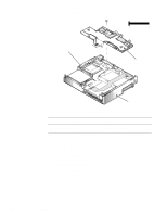
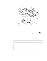
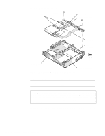
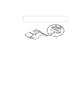
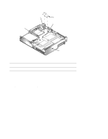
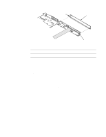
Removing the System Board Assembly To remove the system board assembly, follow these steps: 1. Remove the palmrest assembly. 2. Remove the display assembly. 3. Remove the diskette/CD-ROM assembly. 4. Verify that the PC Card ejectors are fully depressed. 5. Remove the deck buoy plate. (Reinstall this part on the new system board.) CAUTION: To ensure maximum cooling for the microprocessor, do not touch the heat transfer area on the system board above the microprocessor or on the deck buoy plate. The oils in your skin reduce the heat transfer of the thermal pads. 6. Remove the superpart assembly. Carefully disengage the superpart docking EMI and serial EMI clips from the I/O docking EMI and serial EMI clips. 7. Remove screws SB1 and SB2, which retain the system board (see Figure 4-27). 8. Lift the system board approximately 2 inches from the back of the computer. 9. Disengage the front of the system board from the three molded tabs in the bottom case assembly. The tabs' approximate location is shown in Figure 4-27. The tabs are located alongside the hard-disk drive compartment, inside the bottom case assembly. CAUTION: When removing the system board assembly, be careful not to damage the main battery connector and EMI shield on the bottom of the assembly. 10. Lift the system board assembly out of the bottom case assembly. NOTE: If the main battery insulator comes out with the system board assembly, detach the insulator and set it aside. Removing and Replacing Parts 4-39
-
 1
1 -
2
-
3
-
4
-
5
-
6
-
7
-
8
-
9
-
10
-
11
-
12
-
13
-
14
-
15
-
16
-
17
-
18
-
19
-
20
-
21
-
22
-
23
-
24
-
25
-
26
-
27
-
28
-
29
-
30
-
31
-
32
-
33
-
34
-
35
-
36
-
37
-
38
-
39
-
40
-
41
-
42
-
43
-
44
-
45
-
46
-
47
-
48
-
49
-
50
-
51
-
52
-
53
-
54
-
55
-
56
-
57
-
58
-
59
-
60
-
61
-
62
-
63
-
64
-
65
-
66
-
67
-
68
-
69
-
70
-
71
-
 72
72 -
 73
73 -
 74
74 -
 75
75 -
 76
76 -
 77
77 -
 78
78 -
 79
79 -
 80
80 -
 81
81 -
 82
82 -
83
-
84
-
85
-
86
-
87
-
88
-
89
-
90
-
91
-
92
-
93
-
94
-
95
-
96
-
97
-
98
-
99
-
100
-
101
-
102
-
103
-
104
-
105
-
106
-
107
-
108
-
109
-
110
-
111
-
112
-
113
-
114
-
115
-
116
-
117
-
118
-
119
-
120
-
121
-
122
 |
 |
